
Chemical machinery capable of automatically conveying materials and preventing leakage of raw materials

A technology of automatic conveying and chemical machinery, which is applied to mixers, mixers, transportation and packaging with rotary stirring devices, which can solve the inconvenience of simultaneous conveying of multiple raw materials, the inconvenience of mixing and mixing chemical raw materials, and the inconvenience of chemical raw materials. Follow-up production and other problems, to achieve the effect of easy replacement, avoid overflow, and avoid waste

Active Publication Date: 2019-01-08
上海瑞迈企业管理咨询有限公司 +1
View PDF6 Cites 2 Cited by
  • Summary
  • Abstract
  • Description
  • Claims
  • Application Information

AI Technical Summary

Problems solved by technology

[0004] The object of the present invention is to provide a kind of chemical machinery that prevents the leakage of raw materials and automatically conveys materials, to solve the problem that the modern chemical machinery used in the above-mentioned background technology does not have the function of freely conveying raw materials, and it is not convenient to handle various raw materials. Conveying at the same time makes the conveying efficiency of raw materials not good, and does not have the function of stirring and mixing chemical raw materials, which is not convenient for users to follow-up production of chemical raw materials, so that it is not convenient for users to use the chemical machinery.

Method used


Image

  • Chemical machinery capable of automatically conveying materials and preventing leakage of raw materials
  • Chemical machinery capable of automatically conveying materials and preventing leakage of raw materials
  • Chemical machinery capable of automatically conveying materials and preventing leakage of raw materials

Examples


Embodiment Construction

[0027] The following will clearly and completely describe the technical solutions in the embodiments of the present invention in conjunction with the accompanying drawings in the embodiments of the present invention. Obviously, the described embodiments are only some, not all, embodiments of the present invention. Based on the embodiments of the present invention, all other embodiments obtained by persons of ordinary skill in the art without making creative efforts belong to the protection scope of the present invention.

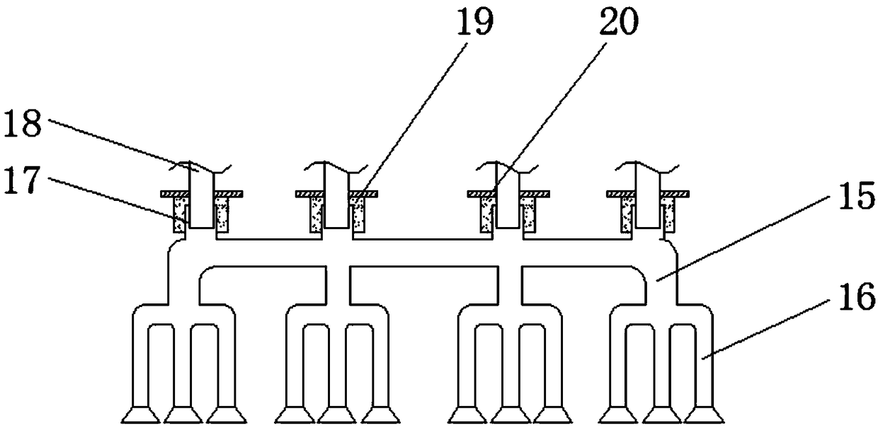
[0028] see Figure 1-6 , the present invention provides a technical solution: a chemical machinery for automatically conveying materials to prevent leakage of raw materials, including a chemical raw material storage tank 1, a drive motor 2, a rotating shaft 3, a first stirring rod 4, a second stirring rod 5, a second stirring rod A stirring blade 6, a second stirring blade 7, a connecting rod 8, a brush roller 9, a brush 10, a mounting block 11, a first moun...


PUM


Abstract

The invention discloses chemical machinery capable of automatically conveying materials and preventing leakage of raw materials. The chemical machinery comprises a chemical raw material storage tank,material feeding ports, connecting pipes, shock absorbing springs and caulking grooves, wherein the upper end of the chemical raw material storage tank is equipped with a driving motor; an output endof the driving motor is connected with a rotating shaft; the outer wall of the rotating shaft is respectively fixed with first stirring rods and second stirring rods; the shock absorbing springs are mounted at the tail ends of second supporting rods; the caulking grooves are formed above the inside of an support base; an anti-collision casing is ranged on an side wall of the chemical raw materialstorage tank; water storage tanks are arranged outside the chemical raw material storage tank; and water pumps are arranged inside the water storage tanks. According to the chemical machinery capableof automatically conveying materials and preventing the leakage of raw materials, since first stirring blades and second stirring blades are arranged in a staggered manner, a stirring effect on chemical raw materials inside the chemical raw material storage tank is achieved, so that the chemical raw materials are uniformly mixed, and the subsequent production of the mixed chemical raw materials for users is facilitated.

Description

technical field [0001] The invention relates to the technical field of chemical machinery, in particular to a chemical machinery for automatically conveying materials that prevents leakage of raw materials. Background technique [0002] Chemical machinery is the general term for machines and equipment used in chemical industrial production. In order to process raw materials into finished products of a certain specification in chemical production, it often needs to go through a series of chemical processes such as raw material pretreatment, chemical reaction, and separation and purification of reaction products. The machinery used to realize these processes is often classified as chemical machinery. Chemical machinery can be divided into the following categories: grinding series, complete set of coating equipment, kneading series, stirring and dispersing series, reaction series, emulsification series, mixing series , dry powder mortar equipment, filtration series, etc. [00...

Claims


Application Information

Patent Timeline
Patent Type & Authority Applications(China)
IPC IPC(8): B01F7/30B01F15/00B01F15/02
CPCB01F27/191B01F27/95B01F35/121B01F35/711B01F35/43
Inventor 胡立波
Owner 上海瑞迈企业管理咨询有限公司
Learn More