
Assembly for securing built-in electronic and electrical devices

A technology for electronic devices and fastening components, which is applied to parts of connecting devices, detachable fasteners for friction clamping, electrical components, etc., and can solve problems such as inability to provide fastening

Inactive Publication Date: 2019-01-04
SIMON SA
View PDF9 Cites 0 Cited by
  • Summary
  • Abstract
  • Description
  • Claims
  • Application Information

AI Technical Summary

Problems solved by technology

[0006] For this second method of fastening by claws, systems are also known in which the claws are separate elements from the frame, to which the different electrical or electronic components to be mounted inside the box are connected, however, the The connection between the jaws and the frame is often performed by screws, which, in addition to the resulting complexity and the need to use tools to perform it, does not provide a completely optimal fastening, since it makes the eventual movement, Movement tends to increase with use, especially when connecting or disconnecting electrical or electronic components

Method used


Image

  • Assembly for securing built-in electronic and electrical devices
  • Assembly for securing built-in electronic and electrical devices
  • Assembly for securing built-in electronic and electrical devices

Examples


Embodiment Construction

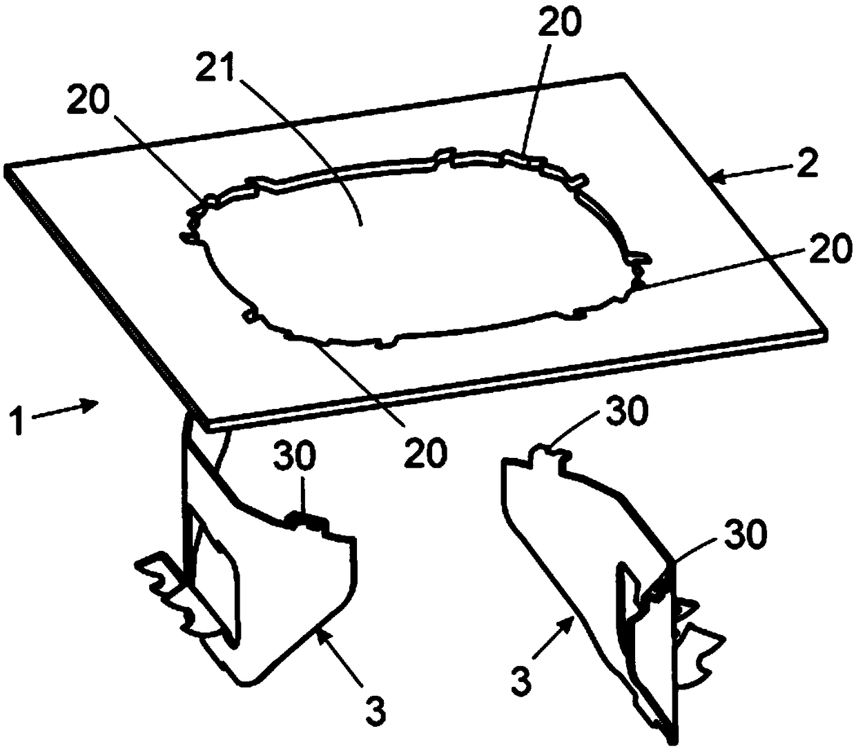
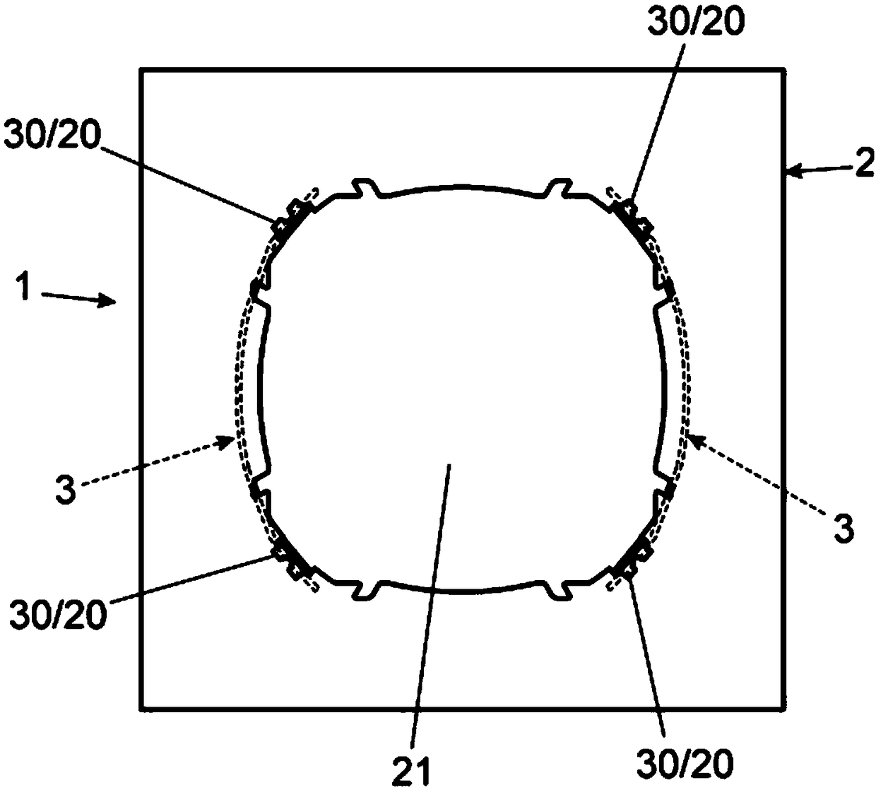
[0025] With reference to said drawings, and according to the numbering adopted therein, non-limiting examples of fastening assemblies for inbuilt electrical and electronic devices of the invention can be seen, comprising the parts and elements detailed and disclosed below.

[0026] Thus, as can be seen in said figures, the assembly (1) in question comprises a frame (2) and at least two claws (3). At least one claw (3) is flexible and independent of the frame (2), and the at least one claw (3) can be connected to the frame (2) by its temporary deformation. When the claw (3) is connected to the frame (2), at least two bearing points, preferably three misaligned bearing points, are created between the claw (3) and the frame (2).

[0027] Preferably, the frame includes at least one hollow portion (21) and at least two supporting points (20), and the claw (3) has at least two supporting points (30), so that the supporting point (30) of the claw (3) In its deformed position it can ...


PUM


Abstract

The invention relates to an assembly for securing built-in electronic and electrical devices. The assembly comprises a frame (2) suitable for securing an electrical and / or electronic device and claws(3) suitable for fixing the frame (2) to the wall or box into which it is built. The assembly has at least two claws (3) of which at least one is flexible and independent of the frame (2) and can be attached to the frame (2) by means of the temporary deformation of the claw (3), thus generating, once attached to the frame (2), at least three non-aligned support points between the claw (3) and theframe (2). The frame (2) comprises at least one hole (21) and at least two holding points (20), and the claw (3) comprises two support points (30) which can be inserted into the hole (21) of the frame(2) when the claw is deformed, and when the claw (3) is released, the support points (30) or clipping tabs coincide with the holding points (20) or slots of the frame (2). The claw (3) has a U-shapedcross section that reduces when pressure is applied, and when the pressure is released, the distance increases and the clipping tabs (30) remain fixed in the slots (20). The tabs (30) have a recess (31). The claw (3) has a groove (34).

Description

[0001] purpose of invention [0002] As stated in the title of this specification, the present invention relates to fastening assemblies for built-in electrical and electronic devices, the functions provided by which fastening assemblies are designed to have the advantages and characteristics which will be disclosed in detail below, which means for An improvement over the state of the art. [0003] The object of the present invention relates to a fastening assembly comprising a frame and claws connected to the frame and allowing fastening of the claws to a built-in box designed to house electrical and / or electronic part and connection to the frame, which has the feature that the claws are connected to the frame by simple pressing and clamping of the two bearing points, since the structural configuration of the two elements is designed to avoid the use of tools needs, thus optimizing the fastening effect and convenience. In addition, the jaws of the assembly proposed by the inv...

Claims


Application Information

Patent Timeline
Patent Type & Authority Applications(China)
IPC IPC(8): H02G3/12H02G3/18
CPCH02G3/121H02G3/18F16B2/243H01R13/6395H01R24/76F16B11/002
Inventor 乔迪·阿德柳·科斯塔斯乔纳坦·阿先·费尔南德斯
Owner SIMON SA
Learn More