
A method and apparatus for automatically generating system network topology

A system network and automatic generation technology, applied in transmission systems, digital transmission systems, data exchange networks, etc., can solve problems such as inefficiency and difficulties

Active Publication Date: 2019-01-04
北京华力创通科技股份有限公司
View PDF6 Cites 2 Cited by
  • Summary
  • Abstract
  • Description
  • Claims
  • Application Information

AI Technical Summary

Problems solved by technology

At present, the systems designed by designers are relatively simple. For the network topology design of complex avionics systems, it is very difficult and inefficient, and the design results directly determine the data transmission performance of the system network.

Method used


Image

  • A method and apparatus for automatically generating system network topology
  • A method and apparatus for automatically generating system network topology
  • A method and apparatus for automatically generating system network topology

Examples


specific Embodiment

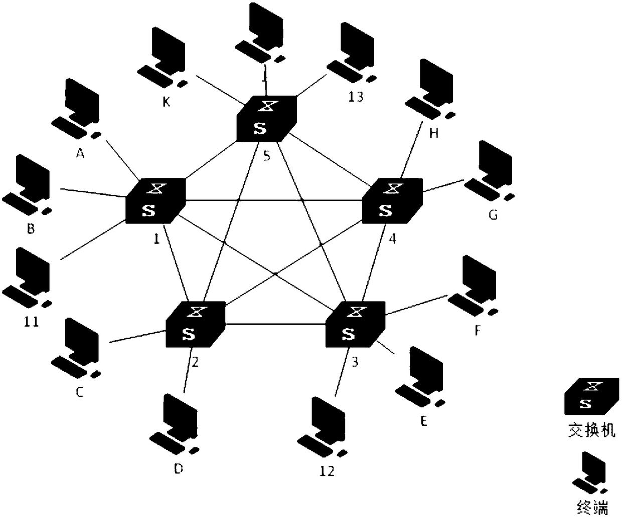
[0103] see image 3 As shown, the embodiment of the present application also provides a specific example of automatic generation of system network topology, including:

[0104] The system network includes 13 terminals, namely terminal A, terminal B, terminal C, terminal D, terminal E, terminal F, terminal G, terminal H, terminal J, terminal K, terminal 11, terminal 12, terminal 13, 5 switches are included, each switch has at least 7 ports, and the number of available ports for connecting terminals is set to 2.

[0105] First connect all the switches in series. All terminals are divided into 5 groups through the system network topology automatic generation method provided by this application, some groups include 2 terminals, some groups include 3 terminals, and more than 3 terminals are included in the group The terminal is not divided into any group at the beginning because the number of connections between the terminal and each seed terminal is relatively small. At this tim...


PUM


Abstract

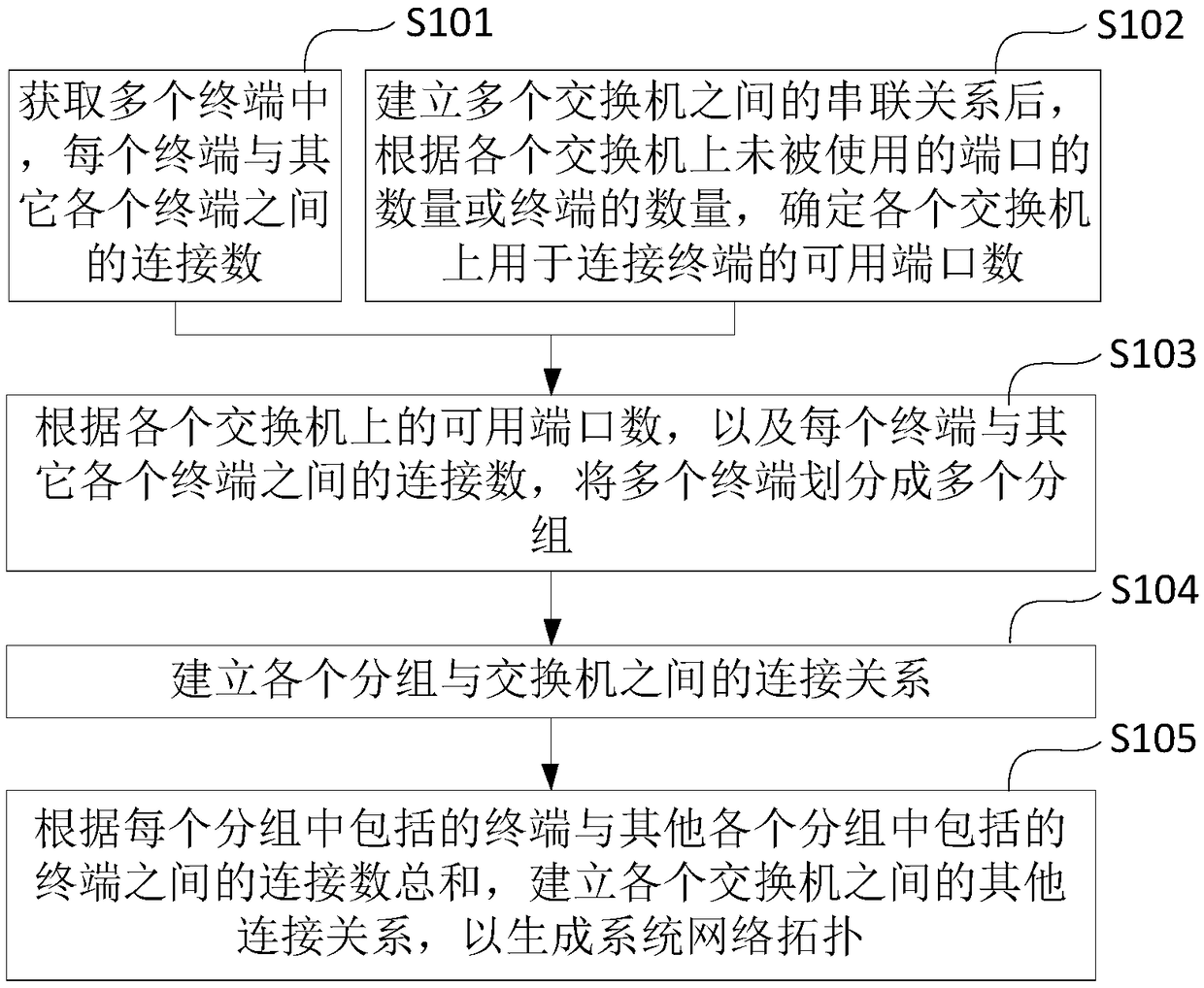
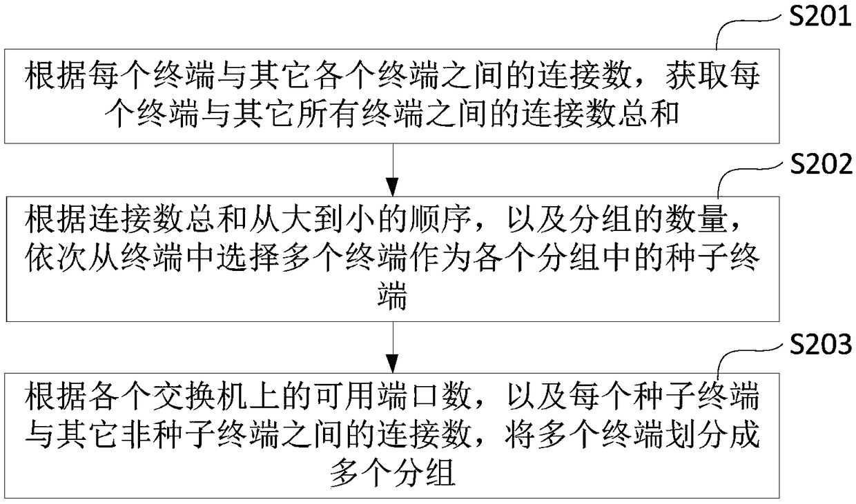
The invention provides a method and a device for automatically generating system network topology, wherein the method comprises the following steps: acquiring the number of connections between each terminal and other terminals in a plurality of terminals; after establishing the serial relationship between switches, determining the number of available ports on each switch for connecting terminals according to the number of unused ports or terminals on each switch; according to the number of available ports on each switch and the number of connections between each terminal and other terminals, dividing the terminals into a plurality of sub-sets; establishing the connection relationship between each sub-set and the switch; and based on the sum of the number of connections between the terminals included in each sub-set and the terminals included in the other sub-sets, establishing other connection relationships between the respective switches to generate a system network topology. The method and the apparatus can automatically generate a network topology of a complex network avionics system, reduce the difficulty of complex network topology generation caused by artificial design, and improve the efficiency of complex network topology design.

Description

technical field [0001] The present application relates to the technical field of network topology design, in particular to a method and device for automatically generating system network topology. Background technique [0002] The network topology (Network Topology) structure refers to the physical layout of various devices interconnected by transmission media, and refers to the specific physical (real) or logical (virtual) arrangement among members of the network. If two networks have the same connection structure, then they have the same network topology. [0003] At present, the network topology design of complex network avionics systems all rely on manual work. The designer will plan the network according to the connection relationship of each terminal in the avionics system, and the technical level of the designer directly determines the effect of the network design. At present, the systems designed by designers are relatively simple. For the network topology design o...

Claims


Application Information

Patent Timeline
Patent Type & Authority Applications(China)
IPC IPC(8): H04L12/24
CPCH04L41/12
Inventor 王雁来方丙武陈亮王传霸路骏
Owner 北京华力创通科技股份有限公司
Learn More