
Beam matching method and communication device

A matching method and technology of communication equipment, applied in the field of communication, can solve problems such as inability to support time-domain transmission beam scanning

Active Publication Date: 2019-01-04
HUAWEI TECH CO LTD
View PDF5 Cites 2 Cited by
  • Summary
  • Abstract
  • Description
  • Claims
  • Application Information

AI Technical Summary

Problems solved by technology

However, only the same sending beam can be sent on consecutive time subunits to realize receiving beam scanning in the time domain, but cannot support sending beam scanning in the time domain

Method used


Image

  • Beam matching method and communication device
  • Beam matching method and communication device
  • Beam matching method and communication device

Examples


Embodiment Construction

[0046] Below in conjunction with accompanying drawing, embodiment of the present invention is described:

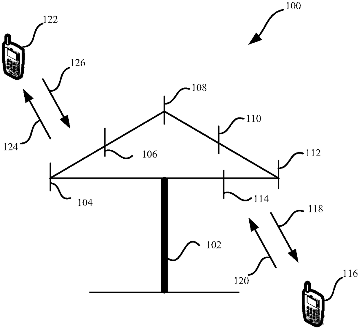
[0047] see figure 1 , figure 1 It is a schematic diagram of a communication system architecture involved in an embodiment of the present invention. The system includes a receiver device and a transmitter device. The receiving end device in the embodiment of the present invention can communicate with one or more core networks via a radio access network (Radio AccessNetwork, RAN), and the receiving end device can refer to an access terminal, a subscriber unit, a subscriber station, a mobile station, a mobile station , remote station, remote terminal, mobile device, user terminal, terminal, wireless communication device, user agent, or user communication device. The access terminal may be a cellular phone, a cordless phone, a Session Initiation Protocol (SIP) phone, a Wireless Local Loop (WLL) station, a Personal Digital Assistant (PDA) , referred to as "PDA"), handheld ...


PUM


Abstract

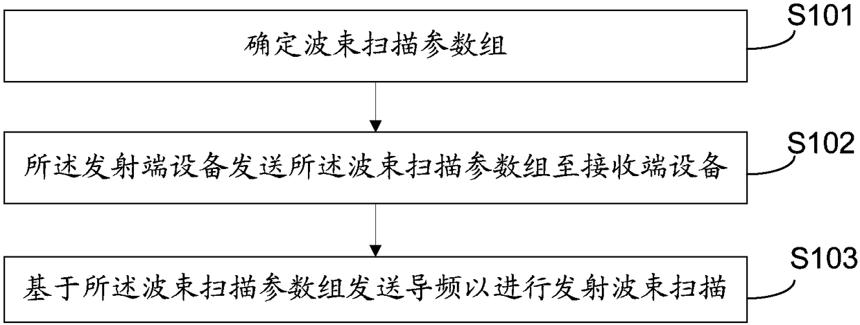
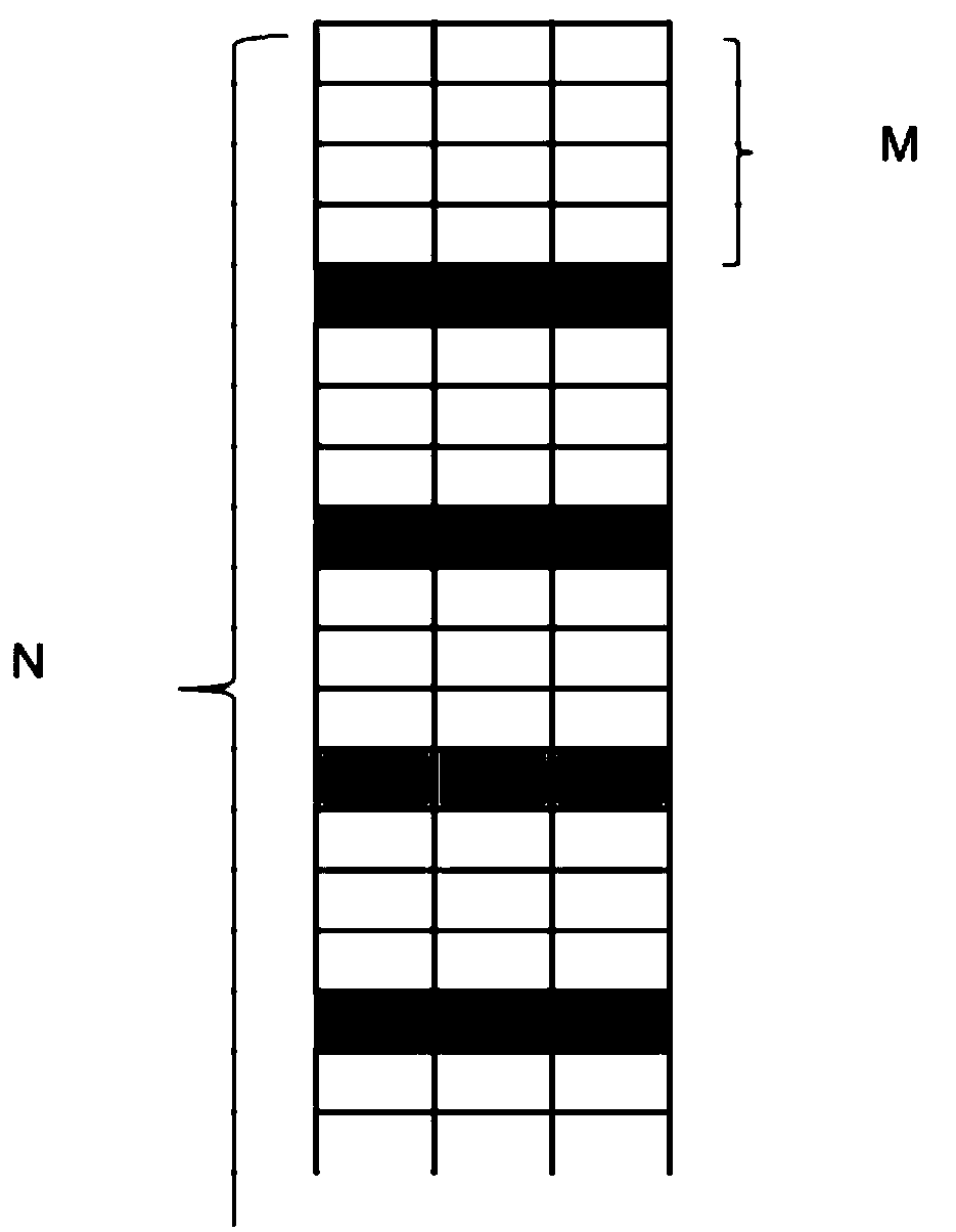
The invention provides a beam matching method and a communication device. The beam matching method includes the following steps that: a beam scanning parameter group is determined, wherein the scanning parameter group includes M, P, and Q, wherein M refers to the number of time-domain repetition signals in one OFDM symbol, P refers to the length of a 0 sequence between two adjacent time-domain repetition signals in the OFDM symbol, and Q refers to the length of the 0 sequence between a cyclic prefix and the first time-domain repetition signal in the OFDM symbol; the beam scanning parameter group is transmitted to a receiving end device; and pilots are transmitted based on the beam scanning parameter group, so that beam scanning can be transmitted or received. With the beam matching methodand the communication device provided by the technical schemes provided by the present invention adopted, some gaps, such as the 0 symbol sequence, can be interpolated to both sides or one side of thetime-domain repetition signals; in addition, due to the presence of the gaps, a traditional interleaved frequency division multiple access (IFDMA) scheme can be improved to support the transmitting or receiving of beam scanning in the time domain.

Description

technical field [0001] The present invention relates to the technical field of communication, in particular to a beam matching method and communication equipment. Background technique [0002] MIMO (multi-input multi-output, multiple input multiple output) technology utilizes resources in the space dimension, which can enable the signal to obtain array gain, multiplexing and diversity gain, and interference cancellation gain in space without increasing the system bandwidth. Double the capacity and spectrum efficiency of the communication system. [0003] In 5G (5 th -generation, fifth-generation mobile communication system) NR (New Radio, new generation air interface technology) solution, MIMO technology that can significantly increase system capacity will still be used as a key technology to meet the high-speed transmission requirements of NR. On the other hand, in the demodulation process at the receiving end of the MIMO communication system, the performance of coherent ...

Claims


Application Information

Patent Timeline
IPC IPC(8): H04B7/0413
CPCH04B7/0413
Inventor 武露刘永
Owner HUAWEI TECH CO LTD
Learn More