
A method for supplementing pulses of valve-based electronic equipment

A valve-based electronic device and trigger pulse technology, which is applied in the direction of electrical components, output power conversion devices, etc., can solve the problems of uncertain timing of trigger pulse reissue, inability to quickly establish a current loop, and uncontrollable establishment of current time, etc., to achieve Solve the random and uncontrollable time, improve the success rate of unlocking, and improve the targeted effect

Inactive Publication Date: 2019-01-04
ELECTRIC POWER RESEARCH INSTITUTE, CHINA SOUTHERN POWER GRID CO LTD
View PDF3 Cites 2 Cited by
  • Summary
  • Abstract
  • Description
  • Claims
  • Application Information

AI Technical Summary

Problems solved by technology

Therefore, the reissuing pulse strategy commonly used in existing valve-based electronic equipment triggers an uncertain timing of reissuing pulses, and the establishment of current time is uncontrollable and has a large randomness. It is impossible to quickly establish a current loop and form a current path.

Method used


Image

  • A method for supplementing pulses of valve-based electronic equipment
  • A method for supplementing pulses of valve-based electronic equipment
  • A method for supplementing pulses of valve-based electronic equipment

Examples


Embodiment Construction

[0018] The following will clearly and completely describe the technical solutions in the embodiments of the present invention with reference to the accompanying drawings in the embodiments of the present invention. Obviously, the described embodiments are only some, not all, embodiments of the present invention. Based on the embodiments of the present invention, all other embodiments obtained by persons of ordinary skill in the art without creative efforts fall within the protection scope of the present invention.

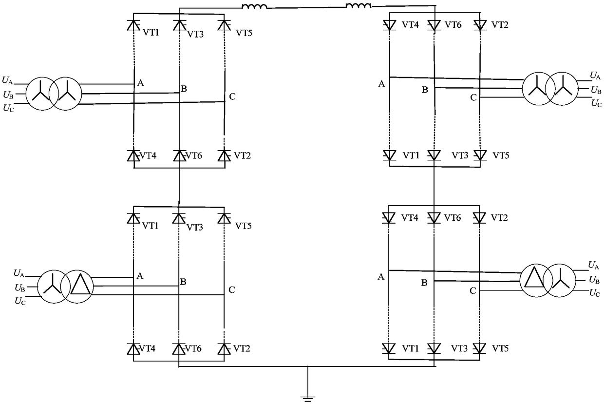
[0019] see figure 1 , which is a schematic diagram of a back-to-back direct current transmission 12-pulse converter valve of a valve-based electronic device reissuing pulse method provided by an embodiment of the present invention, including:

[0020] 12 commutation valves on the rectification side and the reverse flow side, and the rectification side and the reverse flow side are both composed of a Y bridge and a D bridge;

[0021] Since the conduction condition ...


PUM


Abstract

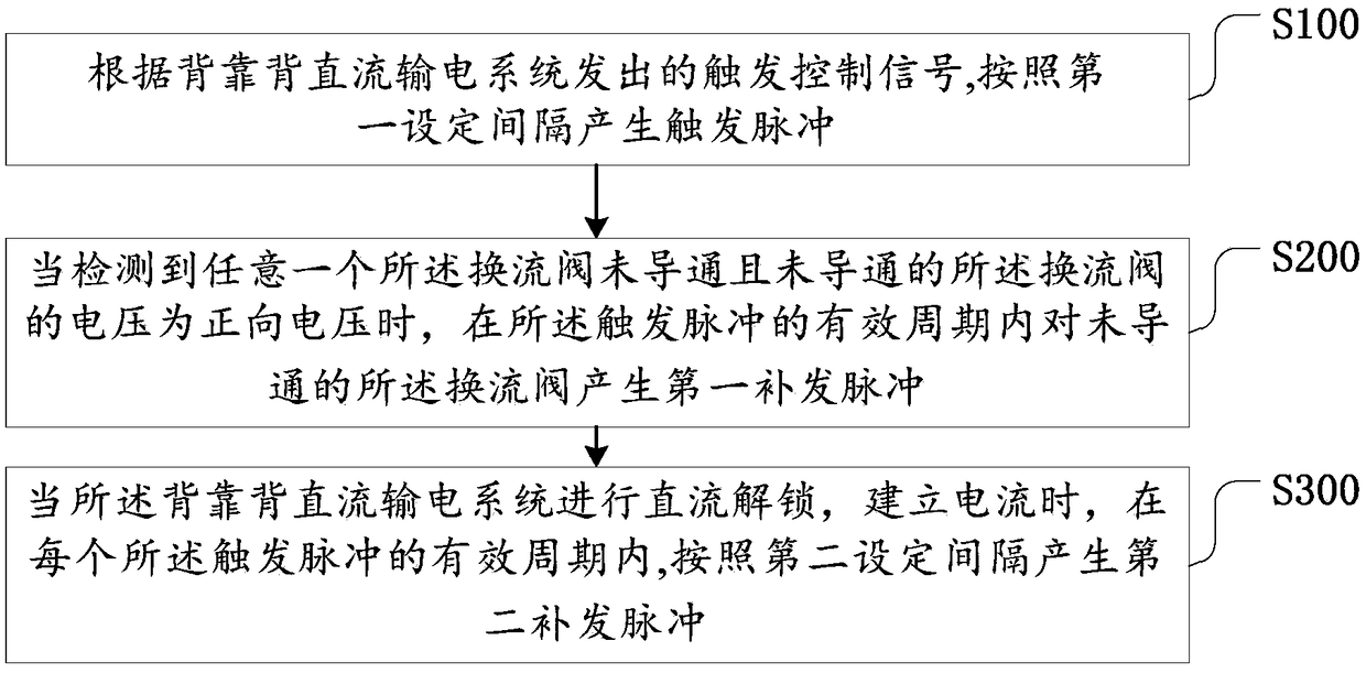
The invention discloses a method for supplementing pulses of valve-based electronic equipment. The method comprises the following steps: generating trigger pulses according to a first set interval according to a trigger control signal emitted by a back-to-back DC transmission system; generating a first supplementary pulse for the non-conductive converter valve within an effective period of the trigger pulse when detecting that any one of the converter valves is not conductive and that the voltage of the non-conductive converter valve is a forward voltage; When the back-to-back DC transmissionsystem is DC unlocked and a current is established, a second supplementary pulse is generated according to a second set interval within an effective period of each of the triggering pulses. The methodgenerates a second supplementary pulse according to a second set interval in each effective period of the triggering pulse, improves the pertinence of the supplementary pulse, effectively solves theproblem that the time of unlocking the establishment current of the back-to-back DC transmission system is random and uncontrollable, improves the unlocking success rate of the back-to-back DC transmission system, and quickly establishes a current loop.

Description

technical field [0001] The invention relates to the technical field of DC power transmission and distribution, in particular to a method for re-issuing pulses of valve-based electronic equipment. Background technique [0002] In the back-to-back DC power transmission system, since the conduction condition of the thyristor converter valve is that the two ends of the valve bear the forward voltage and receive the trigger pulse, when the current is lower than the maintenance current of the valve, the thyristor will be turned off normally, and the back-to-back DC power transmission system When just unlocked, there is no normal freewheeling circuit. In the DC current establishment stage, in order to form a current path, it is necessary to trigger the 4 valve arms on the rectifier side and the 4 valve arms on the inverter side at the same time. The timing cannot meet the above conditions, mainly relying on the supplementary pulse mechanism of the valve-based electronic equipment ...

Claims


Application Information

Patent Timeline
Patent Type & Authority Applications(China)
IPC IPC(8): H02M1/088
CPCH02M1/088
Inventor 刘涛李春华李明陈怡静李婧靓
Owner ELECTRIC POWER RESEARCH INSTITUTE, CHINA SOUTHERN POWER GRID CO LTD
Learn More