
A compensating voltage regulator device and a method for using the compensating voltage regulator device

A voltage stabilizer and compensation technology, applied in the cooling/ventilation of substation/switchgear, AC network voltage adjustment, details of substation/switch layout, etc., can solve the problem of affecting the performance of components and components, and the transmission mode is not stable enough and unstable Input voltage and other issues, to achieve the effect of simple structure, improved service life, and improved accuracy

Inactive Publication Date: 2019-01-04
韩巧女
View PDF0 Cites 0 Cited by
  • Summary
  • Abstract
  • Description
  • Claims
  • Application Information

AI Technical Summary

Problems solved by technology

[0004] According to the level of the input voltage, the voltage regulator automatically applies voltages of different sizes and directions to the compensation excitation coil of the compensation transformer, thereby inducing compensation voltages of different sizes and directions on the compensation coil of the compensation transformer. Finally, the unstable input voltage is superimposed with the compensation voltage to output a relatively stable AC voltage. In the prior art, when adjusting the position of the carbon brush, it is often realized by chain transmission, but this transmission method is not enough. Stable, and the accuracy is not high, and when the regulator is running, it often generates a lot of heat, if it is not discharged in time, it will affect the performance of components

Method used


Image

  • A compensating voltage regulator device and a method for using the compensating voltage regulator device
  • A compensating voltage regulator device and a method for using the compensating voltage regulator device

Examples


Embodiment Construction

[0019] All features disclosed in this specification, or steps in all methods or processes disclosed, may be combined in any manner, except for mutually exclusive features and / or steps.

[0020] Any feature disclosed in this specification, unless specifically stated, can be replaced by other alternative features that are equivalent or have similar purposes. That is, unless expressly stated otherwise, each feature is one example only of a series of equivalent or similar features.

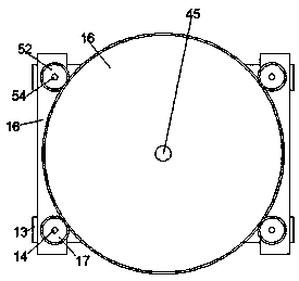
[0021] Such as Figure 1-2As shown, a compensating voltage stabilizer device of the device of the present invention includes a chassis 10, a cavity 11 is arranged in the casing 10, a top plate 43 and a bottom plate 50 are arranged in the cavity 11, and the top plate 43 and the bottom plate 50 are arranged in the cavity 11. A three-phase copper bar 49 is fixedly installed between the bottom plates 50, and the bottom surface of the bottom plate 50 is fixedly mounted with a bottom frame 51 extending fro...


PUM


Abstract

A compensating voltage regulator including chassis, A cavity is arranged in the chassis, A top plate and a bottom plate are arranged in the cavity, Between that top plate and the bottom plate, a three-phase cop bar is fixedly installed, A left-right symmetrical fix mounting of that bottom end surface of the bottom plate is provide with a front-rear extending bottom frame, A left-right symmetricaltop frame is fixedly arrange on that upper end surface of the top plate, At both front and rear end of that top frame, the front and rear ends of the top frame are out of the top plate, At both frontand rear end of that chassis, A lead bar is fixedly installed between that top frame and the bottom frame, The three-phase copper bar is symmetrically provided with a sliding plate which extends leftand right and is slidably matched with a guide rod of a corresponding side, and a carbon brush which is opposed to and slidably matched with the three-phase copper bar is fixedly installed on the sliding plate toward the end face of the three-phase copper bar, and the carbon brush is electrically connected with a compensation transformer installed in the cavity through a cable.

Description

technical field [0001] The invention relates to the field of electric power, in particular to a compensating voltage stabilizer device and a using method thereof. Background technique [0002] Three-phase compensated voltage regulator devices mainly include two types: disc type and column type. Each prior art voltage stabilizer includes: an automatic control circuit, a compensation transformer, a voltage regulator using a motor drive and using carbon brush contact connections. The compensation transformer includes three compensation coils and three compensation excitation coils, and the three compensation coils are respectively located in the three phase lines; the output terminal of the voltage regulator is connected to the compensation excitation coil of the compensation transformer. [0003] The carbon brush and other conductive contact parts slide on the copper wire or copper bar of the voltage regulator. The carbon brush is in different positions, and different output ...

Claims


Application Information

Patent Timeline
Patent Type & Authority Applications(China)
IPC IPC(8): H02J3/12H02B1/56
CPCH02J3/12H02B1/565
Inventor 韩巧女
Owner 韩巧女
Learn More