Eureka AIR delivers breakthrough ideas for toughest innovation challenges, trusted by R&D personnel around the world.

An aircraft fuel tank thermal calculation modeling method and a calculation model thereof

A technology of aircraft fuel tanks and modeling methods, applied in computer-aided design, calculation, design optimization/simulation, etc.

Active Publication Date: 2019-01-04
SHENYANG AIRCRAFT DESIGN INST AVIATION IND CORP OF CHINA
View PDF14 Cites 6 Cited by
  • Summary
  • Abstract
  • Description
  • Claims
  • Application Information

AI Technical Summary

Problems solved by technology

[0004] The object of the present invention is to provide a kind of aircraft fuel tank thermal calculation modeling method and calculation model thereof, to overcome or alleviate the above-mentioned at least one aspect problem

Method used


Image

  • An aircraft fuel tank thermal calculation modeling method and a calculation model thereof
  • An aircraft fuel tank thermal calculation modeling method and a calculation model thereof
  • An aircraft fuel tank thermal calculation modeling method and a calculation model thereof

Examples


Embodiment Construction

[0070] In order to make the objectives, technical solutions and advantages of the present invention clearer, the technical solutions in the embodiments of the present invention will be described in more detail below in conjunction with the drawings in the embodiments of the present invention. In the drawings, the same or similar reference numerals denote the same or similar elements or elements having the same or similar functions throughout. The described embodiments are some, but not all, embodiments of the invention. The embodiments described below by referring to the figures are exemplary and are intended to explain the present invention and should not be construed as limiting the present invention. Based on the embodiments of the present invention, all other embodiments obtained by persons of ordinary skill in the art without creative efforts fall within the protection scope of the present invention. Embodiments of the present invention will be described in detail below ...


PUM


Abstract

The invention relates to the technical field of aircraft fuel thermal management, in particular to an aircraft fuel tank thermal calculation modeling method and a calculation model thereof. A method for modeling the thermal calculation of an aircraft fuel tank comprises the follow steps: 1, abstracting the structure of the aircraft fuel tank as the recapitulative heat transfer boundary 2, making reasonable assumptions about the internal and external heat transfer conditions of the heat exchange boundary; 3, establishing a heat exchange model of that heat exchange boundary according to a reasonable assumption. The heat transfer models of the upper panel, the lower panel and the side panels of the aircraft fuel tank established by this method can be conveniently used for the heat calculationof the aircraft fuel tank, so that they can be incorporated into the heat calculation process of the fuel oil.

Description

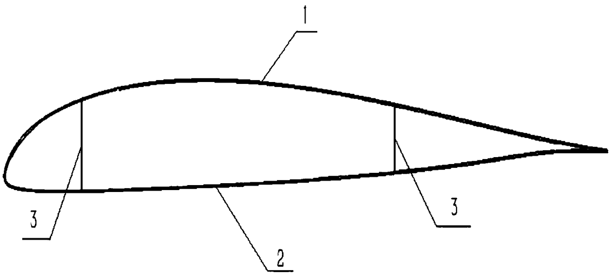
technical field [0001] The invention relates to the technical field of aircraft fuel thermal management, in particular to an aircraft fuel tank thermal calculation modeling method and a calculation model thereof. Background technique [0002] The establishment of aircraft fuel thermal management requires an accurate solution to the temperature change of the fuel in the aircraft fuel tank. The fuel in the aircraft fuel tank exchanges heat with the outside through the fuel tank structure. The heat exchange process includes the heat input from the outside to the fuel through the fuel tank structure and the fuel passing through the fuel tank structure. Heat output to the outside world. [0003] Due to the wide distribution of aircraft fuel tanks on the aircraft, they are installed in the wings, fuselage and engine compartment. The shapes of different parts are very different, and the contact conditions with the internal fuel and the external environment are also different, compl...

Claims


Application Information

Patent Timeline
IPC IPC(8): G06F17/50
CPCG06F2119/08G06F30/20Y02T90/00
Inventor 王亚盟张志伟丁磊徐蕤赵营
Owner SHENYANG AIRCRAFT DESIGN INST AVIATION IND CORP OF CHINA
Why Eureka
Eureka Blog
Learn More