A sliding type inclinometer automatic measurement and positioning structure and its use method

A technology for automatic measurement and positioning of structures, applied in the direction of measuring devices, measuring inclinations, instruments, etc., can solve the problems of difficulty in keeping the standards of reference marks consistent, difficult to ensure position consistency, and deflection of displacement sensors, etc., to achieve automatic The effect of data collection, simplification of inclinometer work and avoidance of deflection

Active Publication Date: 2020-11-10
徐州市帝龙新型墙体材料有限公司
View PDF5 Cites 0 Cited by
  • Summary
  • Abstract
  • Description
  • Claims
  • Application Information

AI Technical Summary

Problems solved by technology

[0004] It can be seen that the disadvantages of the existing sliding inclinometers include: the length mark is used for a long time and is easy to wear due to friction with the nozzle, and the length mark has a certain width, so it is difficult to keep the standard of the reference mark consistent during measurement, that is, It is difficult to guarantee the consistency of the positions of the two measurements
In addition, the length mark is pressed on the nozzle position of the inclinometer tube. At this time, the cable generates an oblique tension on the displacement sensor. Under the action of the horizontal component force of the oblique tension, the displacement sensor will deflect and affect the measurement accuracy (such as figure 2 shown)
Furthermore, when two people measure inclines together, it is easy to rework due to lack of tacit understanding, and it is a great waste of labor costs. At the same time, data cannot be automatically recorded

Method used


Image

  • A sliding type inclinometer automatic measurement and positioning structure and its use method
  • A sliding type inclinometer automatic measurement and positioning structure and its use method
  • A sliding type inclinometer automatic measurement and positioning structure and its use method

Examples


Embodiment 1

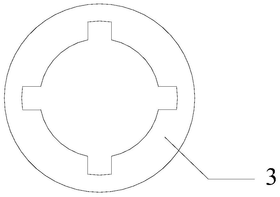
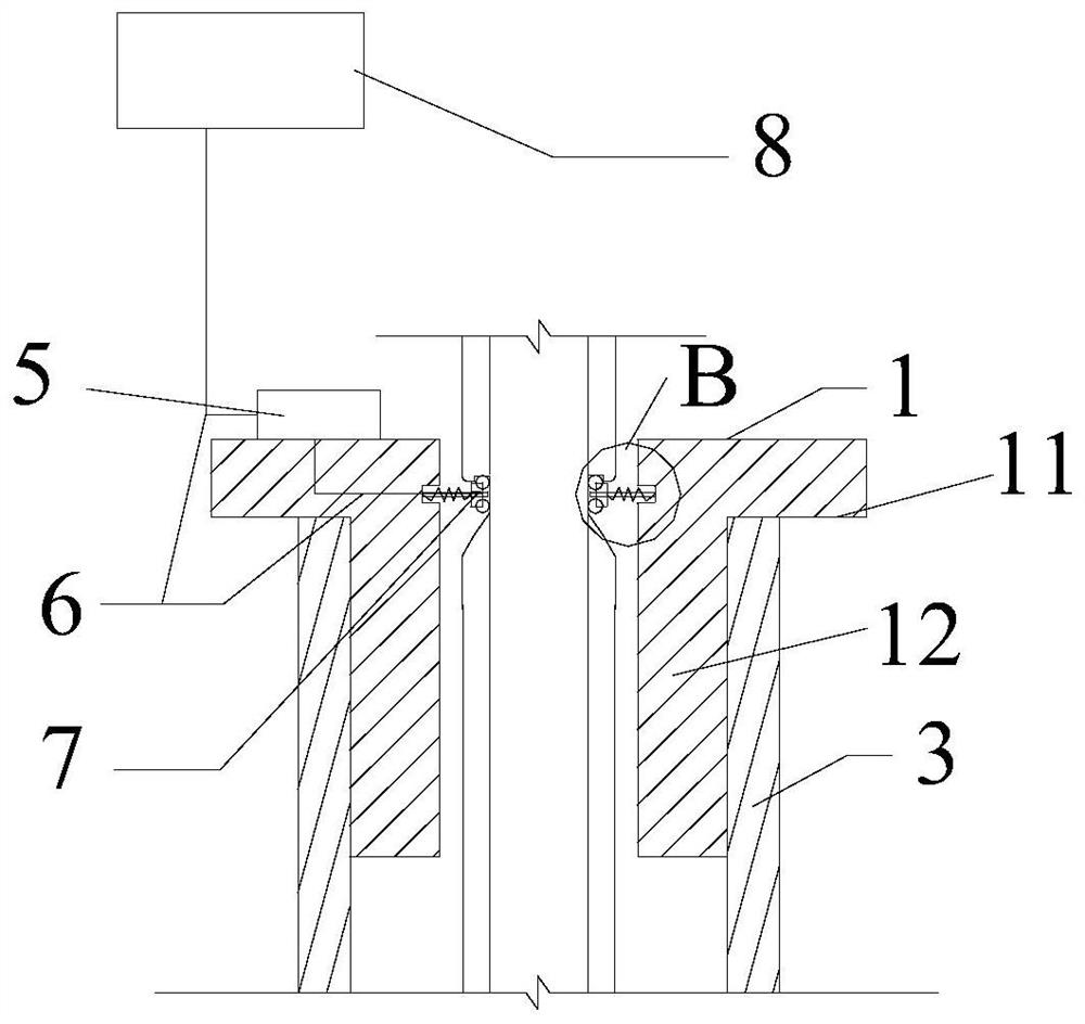
[0052] Such as Figure 3-8 As shown, a sliding inclinometer measurement positioning structure, including positioning cover 1 and cable 2;

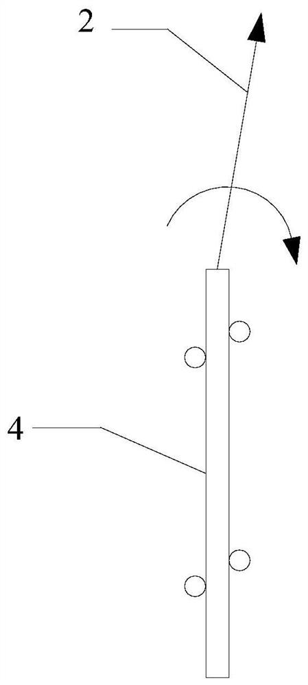
[0053] The positioning cover 1 includes a hollow cylindrical body 12 and a cover edge 11 extending outward from the top of the body 12. The body 12 and the cover edge 11 are integrally formed, and the body 11 is inserted into the nozzle of the inclinometer tube 3. The body 12 and the cover edge 11 are provided with a notch 13 that runs through the inner and outer walls at the same position, and the inner wall of the body 12 is symmetrically provided with a telescopic clamping device 1-1, and the front end of the telescopic clamping device 1-1 is provided with a Roller 1-1-5;

[0054] The first end of the cable 2 is connected to the displacement sensor 4, and the second end is connected to the reading instrument. The cable 2 is equidistantly provided with positioning grooves 21 along the first end to the second end, and the positioning gro...

Embodiment 2

[0068] See attached Figure 3-10 , embodiment 2 is the using method of embodiment 1, comprises the steps:

[0069] (1) Provide a sliding inclinometer with the aforementioned cable 2 and the aforementioned positioning cover 1;

[0070] (2) Open the protective cover of the inclinometer tube, and slowly put the displacement sensor 4 into the bottom of the inclinometer tube 3 through the cable 2;

[0071] (3) Put the cable into the middle of the positioning cover 1 through the gap 13, and put the slide bar 1-1-2 of the telescopic clamping device 1-1 on both sides into the chute 22 of the cable 2 , and then, insert the positioning cover 1 in the nozzle of the inclinometer tube 3, and ensure that the top of the inclinometer tube 3 is attached to the bottom of the cover edge 11;

[0072] (4) Pull the cable so that the telescopic clamping device 1-1 stretches out and snaps into the first positioning groove 21, and then loosens the cable 2. At this time, the slider 1-1-4 triggers the...


PUM


Abstract

The invention relates to an automatic measuring and positioning structure of a sliding inclinometer and a use method of the automatic measuring and positioning structure. The automatic measuring and positioning structure comprises a positioning cover and a cable, wherein telescopic clamping devices are arranged on the positioning cover; positioning grooves are formed in the cable at equal intervals, and each positioning groove is provided with a limit wall and a guide wall; when the positioning grooves of the cable right face the telescopic clamping devices, the telescopic clamping devices extend out and are clamped into the positioning grooves, and the cable position is limited and fixed by the limit walls; when the cable is lifted continuously, rollers of the telescopic clamping devicesslide out of the positioning grooves along the guide walls. The structure is further provided with an automatic data acquisition module and a reminding device electrically connected with the automaticdata acquisition module. The automatic measuring and positioning structure realizes convenient and accurate positioning and can realize automatic measurement, labor cost is reduced effectively, and measuring precision is improved.

Description

technical field [0001] The invention relates to the technical field of safety monitoring, in particular to an automatic measurement and positioning structure of a sliding inclinometer and a use method thereof. Background technique [0002] The sliding inclinometer is an in-situ monitoring instrument for monitoring the horizontal displacement of rock and soil, which can be used to observe the horizontal displacement of rock and soil at different depths in various projects. [0003] The existing sliding type inclinometer includes a cable and a displacement sensor connected to the cable, and a length mark is set every 0.5m or 1m on the outer skin of the cable; when used on site, the displacement sensor is placed in the inclinometer tube and hand-held by manpower cable, and pull the displacement sensor step by step. Each level of measurement needs to rely on the length marking to determine and stabilize the position of the sensor. In order to stabilize the position of the sens...

Claims


Application Information

Patent Timeline
Patent Type & Authority Patents(China)
IPC IPC(8): G01C9/02
CPCG01C9/02
Inventor 吕梅莲
Owner 徐州市帝龙新型墙体材料有限公司
Why Eureka
Try Eureka