Pumping mechanism and sanitary double-ring pump

A technology of dynamic ring and static ring, which is applied in the direction of pumps, pump components, mechanical equipment, etc., can solve the problems of damage to the pump body and flow-passing parts, the balance plate is not lubricated by water, and cannot be completed, so as to improve efficiency and pumping capacity , reduce loss and gas consumption, slow and soft movement effect

Pending Publication Date: 2019-01-04
GUANG ZHOU HYETONE IND TECH CO LTD
View PDF0 Cites 0 Cited by
  • Summary
  • Abstract
  • Description
  • Claims
  • Application Information

AI Technical Summary

Problems solved by technology

[0002] Rotor pumps, gear pumps, diaphragm pumps, and screw pumps used to transport sanitary high-viscosity materials generally use mechanical seals, which fail with changes in material viscosity and temperature, and are prone to wear and tear between the rotor and the stator. Inability to complete online CIP cleaning, poor temperature resistance of sealing materials and other shortcomings, resulting in low efficiency and high energy consumption
In addition, when the pump is idling, the rotating body has no contact or little contact with the medium, so it cannot work effectively, and the liquid cannot be delivered normally. These are all useless work
Because there is no effective work, the load on the motor is very small, and the current generated is also very small. The impact on the motor will not be significant, but the impact of the pump idling on the pump is indeed fatal.
The main manifestations are: 1. The idling pump is easy to cavitate, which will cause damage to the pump body and the flow-through parts; 2. The idling pump will not be lubricated by the liquid, resulting in dry grinding and rapid damage; 3. The idling pump The rotor parts and the pump body generate heat, without the cooling of the liquid, those narrow gap positions (such as: sealing rings) are easy to bite to death due to thermal expansion and contraction; 4. The balance disc of the idling multi-stage centrifugal pump has no water lubrication, and the balance The disk will heat up at a high speed and cause damage

Method used


Image

  • Pumping mechanism and sanitary double-ring pump
  • Pumping mechanism and sanitary double-ring pump
  • Pumping mechanism and sanitary double-ring pump

Examples


Embodiment Construction

[0034] The present invention will be further described in detail below in conjunction with the embodiments and the accompanying drawings, but the embodiments of the present invention are not limited thereto.

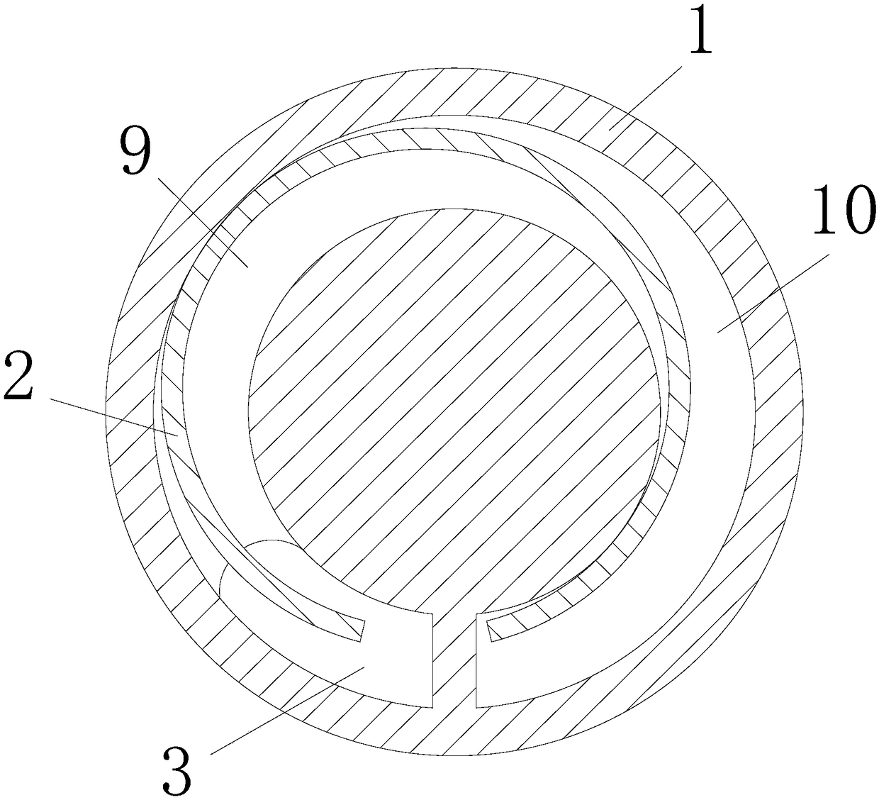
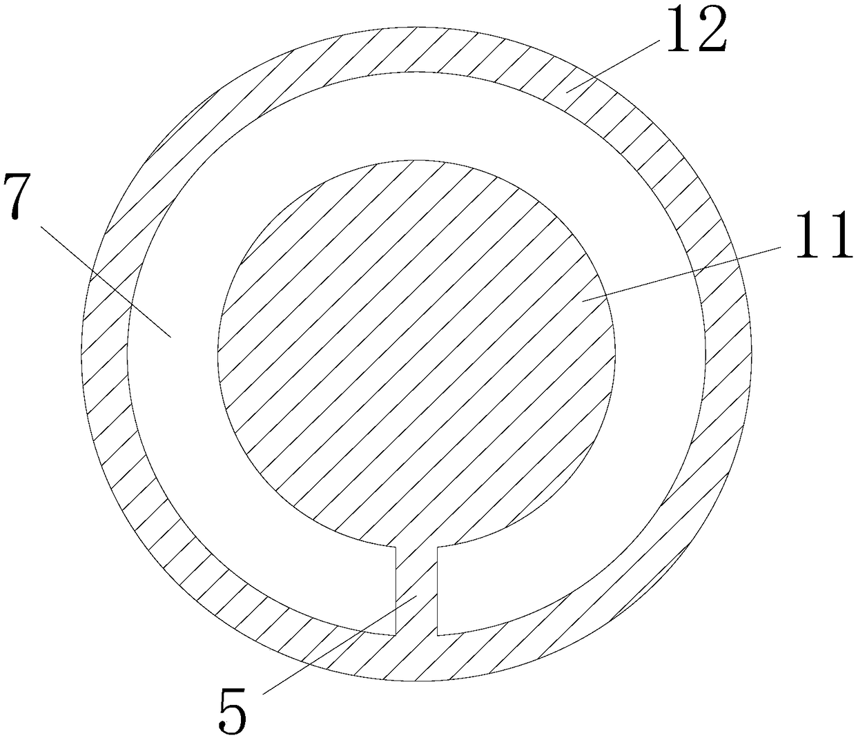
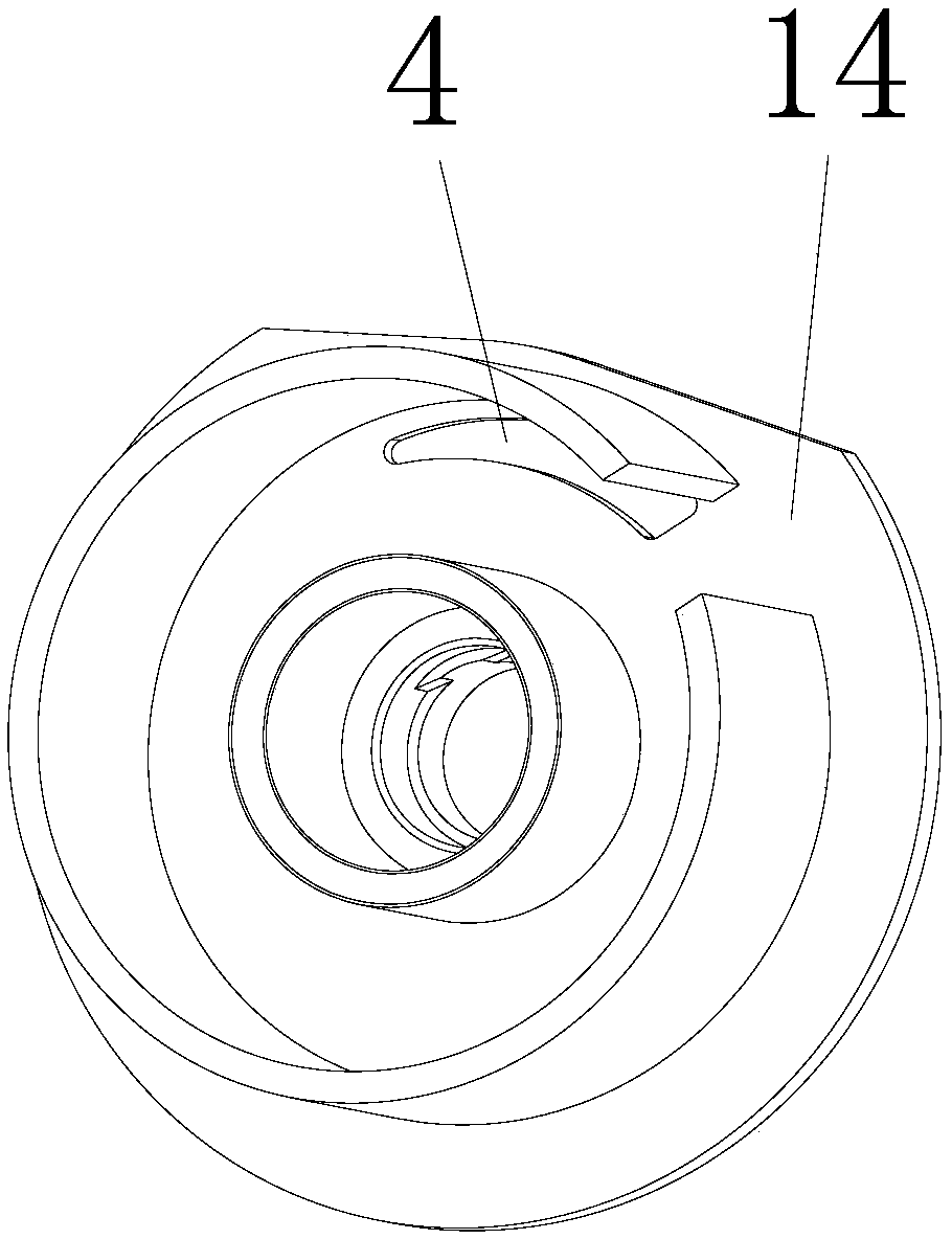
[0035] figure 1 It is a structural schematic diagram of an embodiment of the pumping mechanism of the present invention. A pumping mechanism, comprising: a static ring 1, a movable ring 2 that can swing along the circumferential direction of the wall of the static ring 1, and a partition part arranged between the discharge port 3 and the feed port 4 along the circumferential swing direction of the movable ring 2 5. When the moving ring 2 swings in the circumferential direction, the center of the static ring 1 and the moving ring 2 are staggered, and the moving ring 2 swings in the circumferential direction, forming a gap between the moving ring 2 and the static ring 1 that can convey materials along the swing direction of the moving ring 2. The transmission space 6 and ...


PUM


Abstract

The invention discloses a pumping mechanism and a sanitary double-ring pump, wherein the pumping mechanism includes a fixed ring, a moving ring that may peripherally rock along the wall of the fixed ring, and a partition portion arranged between a discharge port and a feed port along the peripheral rocking direction of the moving ring. With peripheral rocking of the moving ring, a conveying spacecapable of conveying a material along the rocking direction of the moving ring is formed between the moving ring and the fixed ring; the partition portion is used for blocking the material from, alongwith cyclic operation of the conveying space, being sucked into vacuum formed at the feed port by the conveying space after the material is discharged from the discharge port. The fixed ring and themoving ring move gently and slowly so that the pumping mechanism is particularly suitable for pumping media sensitive to shear.

Description

technical field [0001] The invention belongs to the technical field of pumps, in particular to a pumping mechanism and a sanitary double-ring pump. Background technique [0002] Rotor pumps, gear pumps, diaphragm pumps, and screw pumps used to transport sanitary high-viscosity materials generally use mechanical seals, which fail with changes in material viscosity and temperature, and are prone to wear and tear between the rotor and the stator. Inability to complete online CIP cleaning, poor temperature resistance of sealing materials and other shortcomings, resulting in low efficiency and high energy consumption. In addition, when the pump is idling, the rotating body has no or little contact with the medium, so it cannot work effectively, and the liquid cannot be delivered normally, all of which are useless work. Because there is no effective work, the load on the motor is very small, and the current generated is also very small, which will have no effect on the motor, but...

Claims


Application Information

Patent Timeline
Patent Type & Authority Applications(China)
IPC IPC(8): F04C2/02F04C15/00
CPCF04C2/02F04C15/00F04C15/0003
Inventor 胡欣钧王超陈云王坤卢浩荣
Owner GUANG ZHOU HYETONE IND TECH CO LTD
Why Eureka
Try Eureka