Membrane thickness monitoring device and membrane formation equipment

A monitoring device and film thickness technology, applied in ion implantation plating, metal material coating process, coating and other directions, can solve the problems of large film thickness monitoring error, inaccurate film thickness monitoring, large rate fluctuation and so on

Active Publication Date: 2019-01-04
BOE TECH GRP CO LTD
View PDF6 Cites 7 Cited by
  • Summary
  • Abstract
  • Description
  • Claims
  • Application Information

AI Technical Summary

Problems solved by technology

With the increase of the deposition quality of the layer structure material on the crystal oscillator, the vibration frequency of the crystal oscillator will decrease, resulting in a large error in film thickness monitoring
After the service life of the crystal oscillator expires, the cavity needs to be opened for replacement, which affects the production progress
Too fast material deposition on the crystal oscillator will shorten the service life of the crystal oscillator (Lifetime), and too slow will cause large rate fluctuations, resulting in inaccurate film thickness monitoring, resulting in difficult to reconcile contradictions

Method used


Image

  • Membrane thickness monitoring device and membrane formation equipment
  • Membrane thickness monitoring device and membrane formation equipment

Examples


Embodiment 1

[0027] This embodiment provides a film thickness monitoring device. The film thickness monitoring device prolongs the service life of the crystal vibrating plate and improves the crystal vibrating plate on the premise of ensuring the accuracy of film thickness monitoring by adjusting the forming amount of the shielding plate and the film forming material. Use efficiency.

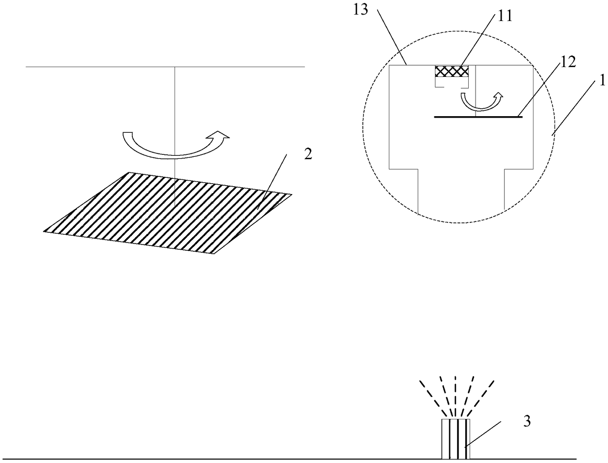
[0028] Such as figure 1 As shown, the film thickness monitoring device includes a film thickness synchronization unit, the film thickness synchronization unit includes a sensor 11 and a shutter 12 (Shutter), the shutter 12 is provided with a plurality of monitoring holes 121, the shutter 12 can move relative to the sensor 11, The orifices of at least two different monitoring holes 121 can be arranged opposite to the sensor 11 to monitor the amount of film-forming material passing through the monitoring holes 121 and reaching the sensor 11 within a set time.

[0029] When the film thickness monitoring device...

Embodiment 2

[0039] This embodiment also provides a film forming device, which can greatly improve the precision control of the film thickness by using the film thickness monitoring device in the first embodiment.

[0040] The film forming equipment includes a film forming material source and a film thickness monitoring device, such as figure 2 As shown, the film thickness monitoring device is the film thickness monitoring device 1 in Embodiment 1, and the film-forming material from the film-forming material source reaches the sensor 11 through the monitoring hole 121 of the blocking plate 12 .

[0041] As an example, the film-forming equipment can be, for example, evaporation equipment, which is adapted to the technological process of a modern production enterprise. The film-forming material source includes at least one evaporation crucible 3, and the evaporation crucible 3 is used to accommodate the evaporation material. Each plating crucible 3 is correspondingly provided with a film th...


PUM


Abstract

The invention belongs to the technical field of display and in particular relates to a membrane thickness monitoring device and membrane formation equipment. The membrane thickness monitoring device comprises a membrane thickness synchronizing unit, wherein the membrane thickness synchronizing unit comprises a sensor and a shielding plate; a plurality of monitoring holes are formed in the shielding plate; the shielding plate is capable of being moved relative to the sensor to enable openings of at least two different monitoring holes to be aligned to the sensor, and then the quantity of a membrane formation material which passes through the monitoring holes and reaches the sensor within a set time is monitored; the sensor is a crystal oscillator. By adopting the membrane thickness monitoring device, on premise that the membrane thickness monitoring accuracy is ensured, the service life of the crystal oscillator is prolonged, and the use efficiency of the crystal oscillator is improved;by adopting the membrane formation equipment, a tool coefficient value matched with an opening radius of the monitoring holes in the shielding plate in the membrane thickness monitoring device is selected, a material on the crystal oscillator is not settled too rapidly or too slowly, a stable membrane formation velocity is maintained, and accurate membrane thickness monitoring can be achieved.

Description

technical field [0001] The invention belongs to the field of display technology, and in particular relates to a film thickness monitoring device and film forming equipment. Background technique [0002] OLED (Organic Light-Emitting Diode: organic light-emitting diode) compared with LCD (Liquid Crystal Display: liquid crystal display device), has a wide color gamut, fast response, wide viewing angle, foldable and other advantages, so it attracts many manufacturers to invest a lot of money develop it. At present, some display products and lighting products on the market have adopted OLED technology, which is likely to replace LCD and become the next-generation mainstream display. [0003] At present, the manufacturing process of OLED devices is mainly thermal evaporation (Evaporation), that is, the layer structure material is heated at high temperature, and the thickness of the layer structure material is monitored at the same time, so as to form the layer structure of the OL...

Claims


Application Information

Patent Timeline
IPC IPC(8): C23C14/24C23C14/54
CPCC23C14/243C23C14/546
Inventor 晏荣建王志东张俊瑞
Owner BOE TECH GRP CO LTD
Why Eureka
Try Eureka