Optical fiber wiredrawing annealing device

An annealing device and wire drawing technology, which is applied in the field of optical fiber drawing, can solve problems such as temperature gradient control, optical fiber fluctuation, and flow field chaos in the tube, and achieve the effects of reducing optical fiber vibration, stable air flow, and good warpage

Pending Publication Date: 2019-01-04
杭州金星通光纤科技有限公司
View PDF12 Cites 6 Cited by
  • Summary
  • Abstract
  • Description
  • Claims
  • Application Information

AI Technical Summary

Problems solved by technology

The above patents have increased the annealing time to a certain extent, slowed down the cooling rate, but cannot control the temperature gradient, and are greatly affected by the air flow path and flow rate of the protective gas in the wire drawing furnace. The vacuum device mentioned in the patent CN 107082560A has To a certain extent, it will cause chaos in the flow field in the tube and cause fluctuations in the optical fiber

Method used


Image

  • Optical fiber wiredrawing annealing device
  • Optical fiber wiredrawing annealing device

Examples


Embodiment 1

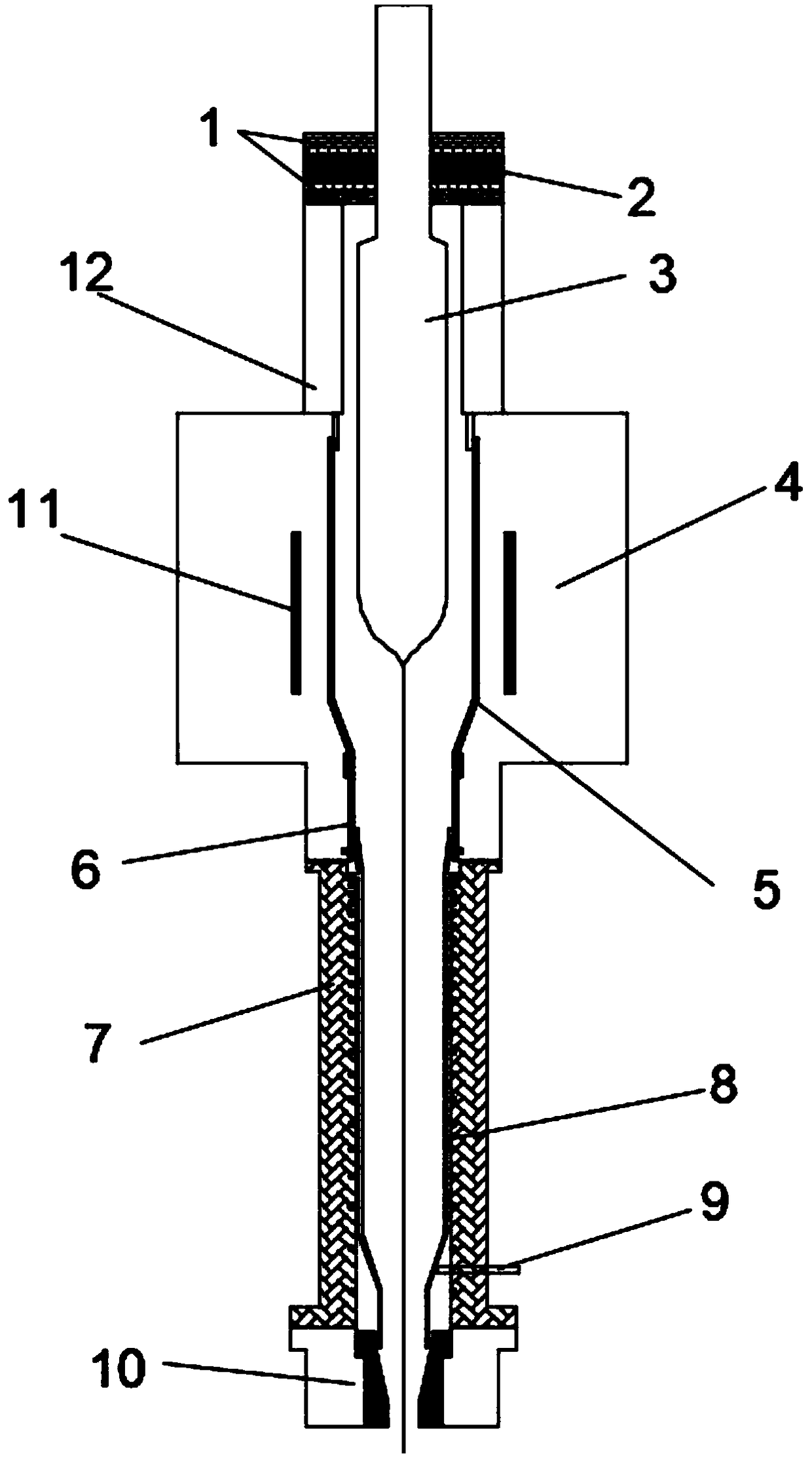
[0029] as attached figure 1 The optical fiber drawing and annealing device shown includes a buffer cylinder 12 at the upper end of the graphite drawing furnace 4, a graphite ring 1, a graphite soft felt 2, a formed graphite tube 5, a graphite connecting tube 6, an annealing furnace 7, a glass guide tube 8, and a measuring tube. Thermocouple 9, sealing ring 10. The inner diameter of the heating body 11 is 320 mm, and the height of the heating body is 280 mm; the inner diameter of the graphite forming tube 5 is 250 mm, the thickness is 6 mm, the length of the tapered surface is 180 mm, and the inner diameter of the bottom is 80 mm; the inner diameter of the buffer tube 12 is 230 mm, and the height is 2200 mm; The diameter of the handle rod of the optical fiber preform 3 is 60mm, and the size error is controlled within 0.2mm; the inner diameter of the graphite ring 1 is 60.5mm, the outer diameter is 360mm, and the thickness is 10mm; the inner diameter of the graphite soft felt 2 ...

Embodiment 2

[0032] as attached figure 1 The optical fiber drawing and annealing device shown includes a buffer cylinder 12 at the upper end of the graphite drawing furnace 4, a graphite ring 1, a graphite soft felt 2, a formed graphite tube 5, a graphite connecting tube 6, an annealing furnace 7, a glass guide tube 8, and a measuring tube. Thermocouple 9, sealing ring 10. The inner diameter of the heating body 11 is 180 mm, and the height of the heating body is 180 mm; the inner diameter of the graphite forming tube 5 is 120 mm, the thickness is 4 mm, the length of the tapered surface is 100 mm, and the inner diameter of the bottom is 50 mm; the inner diameter of the buffer tube 12 is 110 mm, and the height is 1000 mm; The diameter of the handle rod of the optical fiber preform 3 is 50 mm, and the size error is controlled within 0.2 mm; the inner diameter of the graphite ring 1 is 50.5 mm, the outer diameter is 200 mm, and the thickness is 10 mm; the inner diameter of the graphite soft fe...


PUM

PropertyMeasurementUnit
thicknessaaaaaaaaaa
heightaaaaaaaaaa
diameteraaaaaaaaaa

Abstract

The embodiment of the invention discloses an optical fiber wiredrawing annealing device. The device can be used for processing optical fiber preforms. The optical fiber wiredrawing annealing device comprises a graphite wiredrawing furnace, a buffer cylinder disposed at the upper end of the graphite wiredrawing furnace, and an annealing furnace disposed at the lower end of the graphite wiredrawingfurnace, wherein the upper end of the buffer cylinder is provided with a sealing member; a shaped graphite tube is disposed in the graphite wiredrawing furnace; a glass guiding tube is disposed in theannealing furnace; and a graphite connecting pipe for connecting the shaped graphite tube with the glass guiding tube is further disposed in the graphite wiredrawing furnace. According to the opticalfiber wiredrawing annealing device provided by the embodiment of the invention, a spiral heating wire is mounted in the annealing furnace, the thread pitch of the heating wire is linearly increased from top to bottom, the heating power of the heating wire can be adjusted, and a predetermined control requirement can be met according to the feedback of a temperature thermocouple, therefore, an expected temperature gradient in an annealing tube can be obtained, the annealing speed and the temperature reduction gradient in the furnace after formation of the optical fiber are guided, and the acquisition of the optical fiber with small internal stress, small attenuation and good warpage is facilitated.

Description

technical field [0001] The invention relates to the field of optical fiber drawing technology, in particular to an optical fiber drawing annealing device. Background technique [0002] Optical fiber drawing is a process in which the diameter of quartz glass changes from about 60 to 200mm to 125um. This physical change needs to be carried out in a high-temperature furnace, and the temperature in the furnace must reach above 2000°C. In order to continuously reduce production costs, the diameter of optical fiber preforms has reached 200mm or even larger, and the drawing speed has also increased from 1000m / min 20 years ago to 3000m / min. As the size of the optical fiber preform continues to increase and the drawing speed increases, the furnace temperature required for optical fiber drawing continues to rise above 2200°C, and the forming cone of the optical fiber is also continuously lengthening. [0003] After the optical fiber reaches a diameter of 125um, it will go through a c...

Claims


Application Information

Patent Timeline
Patent Type & Authority Applications(China)
IPC IPC(8): C03B25/00C03B37/02
CPCC03B25/00C03B37/02
Inventor 张学军
Owner 杭州金星通光纤科技有限公司
Why Eureka
Try Eureka