
Finished product conveying device for mold production

A technology for conveying devices and finished products, which is applied in the direction of conveyors, transportation and packaging, etc., can solve the problems of unfavorable use, low efficiency, low efficiency, etc., and achieve the effects of facilitating clamping work, broad market prospects, and huge economic benefits

Inactive Publication Date: 2019-01-04
周玉翔
View PDF8 Cites 2 Cited by
  • Summary
  • Abstract
  • Description
  • Claims
  • Application Information

AI Technical Summary

Problems solved by technology

[0002] Mold, various molds and tools used in industrial production for injection molding, blow molding, extrusion, die-casting or forging forming, smelting, stamping and other methods to obtain the required products. After using the mold to produce tools, the finished products need to be transported and stored for Subsequent use, and most mold transport devices are not only cumbersome but also inefficient, so there is an increasing demand for finished product conveyors for mold production
[0003] Most of the finished product conveying devices for mold production on the market are mostly manually transported when the finished products reach a certain amount, which is not conducive to saving labor force, but also has low efficiency. The traditional finished product conveying devices for mold production are inconvenient for conveying, and The noise generated in the process is relatively large, which will cause serious harm to the human body and is not conducive to use. Therefore, in view of the above problems, a finished product conveying device for mold production is proposed.

Method used


Image

  • Finished product conveying device for mold production
  • Finished product conveying device for mold production
  • Finished product conveying device for mold production

Examples


Embodiment Construction

[0018] The following will clearly and completely describe the technical solutions in the embodiments of the present invention with reference to the accompanying drawings in the embodiments of the present invention. Obviously, the described embodiments are only some, not all, embodiments of the present invention. Based on the embodiments of the present invention, all other embodiments obtained by persons of ordinary skill in the art without making creative efforts belong to the protection scope of the present invention.

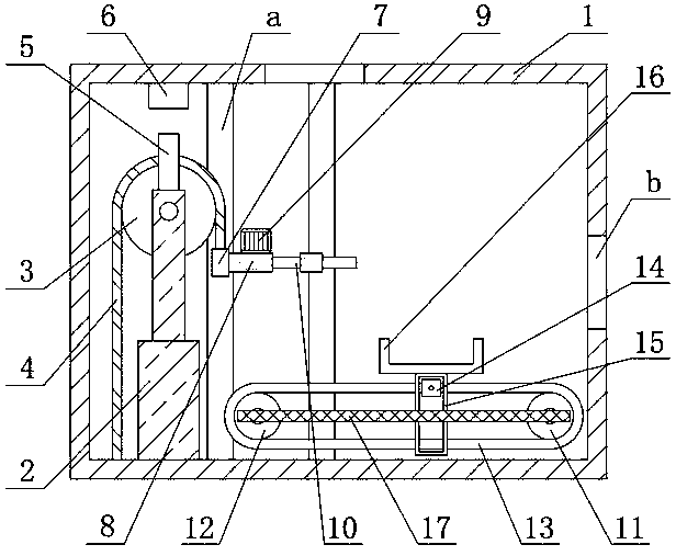
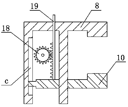
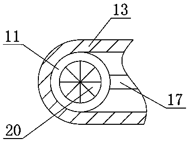
[0019] see Figure 1-3 , the present invention provides a technical solution:

[0020] A finished product conveying device for mold production, comprising a box body 1 and an electric telescopic rod 2, the inner side of the bottom end surface of the box body 1 is fixedly connected with the electric telescopic rod 2, and the front end surface of the electric telescopic rod 2 is rotatably connected with a sprocket 3. A chain 4 is engaged with the outside of the...


PUM


Abstract

The invention relates to the technical field of conveying device, in particular to a finished product conveying device for mold production. The finished product conveying device for mold production comprises a tank and an electric telescopic rod; the inner side of the bottom end face of the tank is fixedly connected with an electric telescopic rod; the front end face of the electric telescopic rodis rotationally connected with a chain wheel; the outer side of the chain wheel is engaged with a chain; the top end of the electric telescopic rod is fixedly connected with a contact; the inner sideof the top end face of the tank is fixedly connected with a touch switch; the bottom end of the right side of the chain is fixedly connected with a slide block; the right end of the slide block is fixedly connected with a fixing frame; the inner side of the fixing frame is in sliding connection with a clamping rod; and a driving chain wheel is arranged on the inner side of the rear end face of the tank. Through the chain, the electric telescopic rod, the clamping rod and the fixing frame, the clamping rod can conveniently clamp produced finished products, in addition, the gear and rack structure is compact, working is reliable, clamping work is facilitated, great economic benefits and wide market prospects are achieved, and the device is worthy of being applied and popularized.

Description

technical field [0001] The invention relates to the technical field of conveying devices, in particular to a finished product conveying device for mold production. Background technique [0002] Mold, various molds and tools used in industrial production for injection molding, blow molding, extrusion, die-casting or forging forming, smelting, stamping and other methods to obtain the required products. After using the mold to produce tools, the finished products need to be transported and stored for For subsequent use, most mold transport devices are not only cumbersome but also inefficient, so there is an increasing demand for finished product conveyors for mold production. [0003] Most of the finished product conveying devices for mold production on the market are mostly manually transported when the finished products reach a certain amount, which is not conducive to saving labor force, but also has low efficiency. The traditional finished product conveying devices for mold...

Claims


Application Information

Patent Timeline
Patent Type & Authority Applications(China)
IPC IPC(8): B65G23/24B65G17/12
CPCB65G17/12B65G23/24
Inventor 周玉翔
Owner 周玉翔
Learn More