
Novel accessory derusting equipment and working method thereof

A technology of parts and equipment, which is applied in the field of new parts derusting equipment, can solve the problems of large environmental investment, high price of shot blasting equipment, immovability and other problems, and achieves the effect of low cost, low noise and no dust.

Pending Publication Date: 2019-01-04
中通新能源汽车有限公司
View PDF0 Cites 2 Cited by
  • Summary
  • Abstract
  • Description
  • Claims
  • Application Information

AI Technical Summary

Problems solved by technology

[0002] Corrosion of parts often occurs in industrial production. The corroded surface must be treated before painting or other surface treatment processes. Therefore, a variety of rust removal processes and equipment have appeared. In the existing technology, surface shot blasting is mostly used. treatment, chemical pre-treatment (pickling, etc.), etc., but these rust removal methods in the prior art have certain disadvantages, such as surface shot blasting treatment, shot blasting equipment is expensive, immovable, and noisy, The energy consumption is also relatively high, and there is a certain amount of environmental pollution; while the chemical pretreatment will produce waste liquid and other chemical pollutants, which will pollute the environment, and the investment in environmental governance in the later stage will be large

Method used


Image

  • Novel accessory derusting equipment and working method thereof
  • Novel accessory derusting equipment and working method thereof
  • Novel accessory derusting equipment and working method thereof

Examples


Embodiment 1

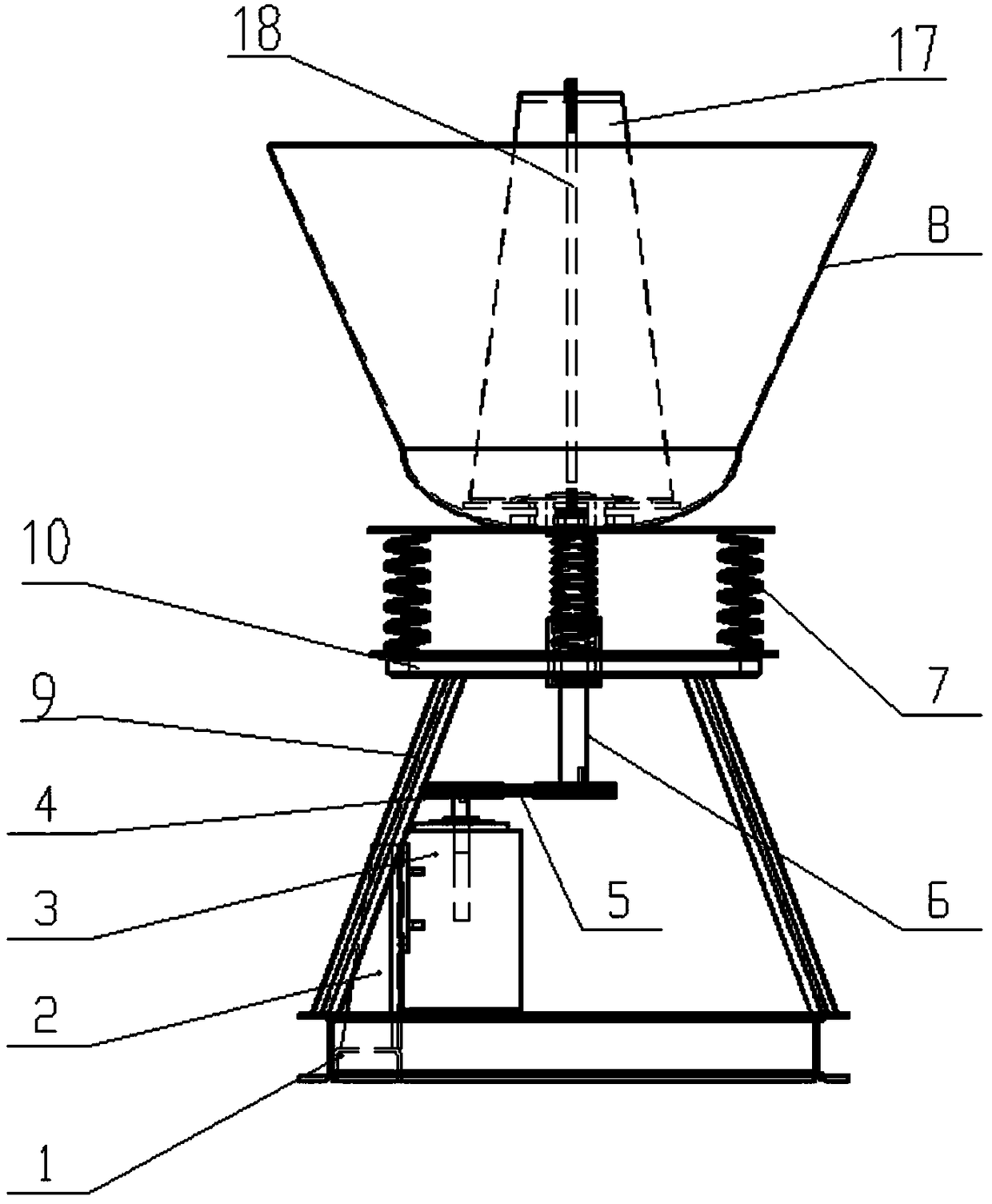
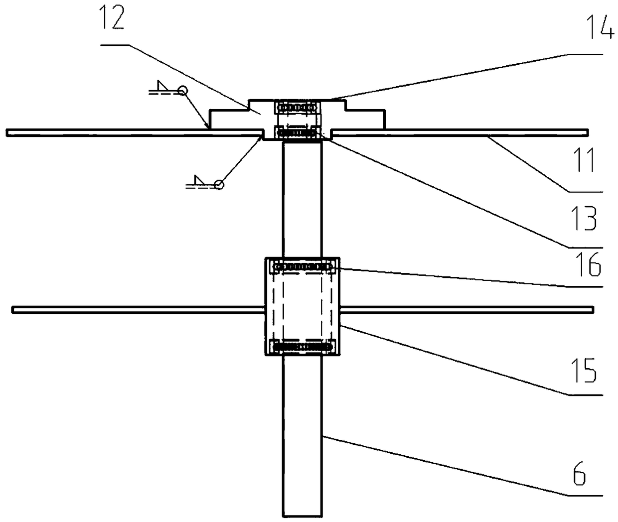
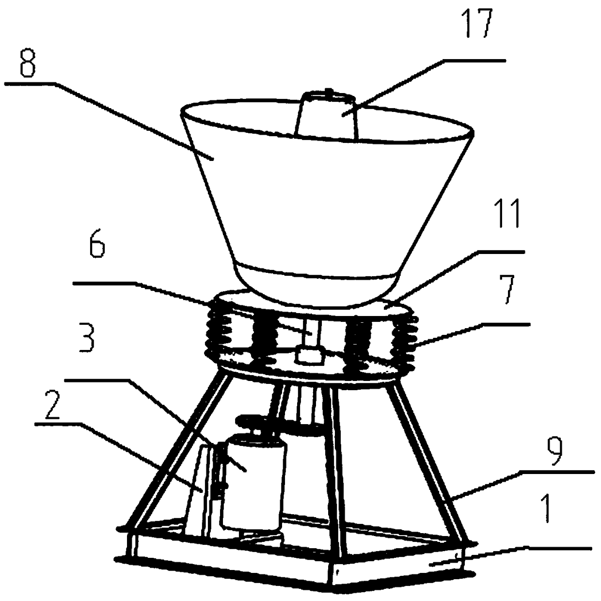
[0020] See attached Figure 1-3 , a new type of parts derusting equipment provided by the present invention is characterized in that, when in use, the equipment base 1 is fixed to the ground with expansion bolts; on the equipment base 1, a bracket 9 is welded and connected, and in the space inside the bracket , a motor 3 is fixed; the motor circuit is connected with a frequency converter, the frequency converter model: PST350-2.2G, rated power 2.2KW, the motor 3 is fixed in the space of the bracket 9 through the motor fixing plate 2, the The motor fixing plate 2 is fixed on the equipment base 1; the output shaft of the motor 3 is connected with a pulley 4, which is connected with the pulley on the eccentric shaft 6 through a belt 5; the eccentric shaft 6 is connected after passing through the fixing plate 10 On the vibrating tray 11, the fixed plate 10 is circular and connected to the eccentric shaft 6. The structure is: a hole is opened in the middle of the fixed plate 10, an...

Embodiment 2

[0022] The working method of the rust removal equipment for the above parts:

[0023] Use the frequency converter to control the motor 3 to drive the eccentric shaft 6 to rotate. The rotation of the eccentric shaft 6 causes vibration, which makes the part container 8 vibrate. At the same time, with the action of the spring 7, put the corroded parts and steel shot and steel sand with different diameters into the part container. , The vibration of the parts container 8 makes the parts fully contact and rub with the steel shot and steel grit, so as to realize the derusting of the parts.


PUM


Abstract

The invention provides novel accessory derusting equipment. A bracket is connected with an equipment base. A motor is fixed into a bracket forming space. An output shaft of the motor is connected witha belt wheel, and is connected with a belt wheel at an eccentric shaft through a belt. The eccentric shaft penetrates through a fixing plate, and then is connected with a vibration tray. The structure of the connecting position between the vibration tray and the eccentric shaft is arranged to be that a flange disc is fixedly connected to the vibration tray; a hole is formed in the center of the flange disc and the vibration tray; a first beating protection sleeve is mounted in the hole; and the eccentric shaft is mounted in the first bearing protection sleeve through a first bearing. Supporting springs are fixed between the fixing plate and the vibration tray. An accessory container is fixedly connected with the vibration tray. The accessory container is internally provided with steel balls with different diameters and steel emery. The invention further provides a working method the the accessory derusting equipment. The accessory derusting equipment is easy to manufacture and is lowin cost, is convenient to use, and is free of pollution. Indistinguishable derusting to special-shaped accessories can be achieved.

Description

technical field [0001] The invention belongs to the technical field of maintenance equipment for mechanical parts, in particular to a novel rust removal equipment for parts and a working method thereof. Background technique [0002] Corrosion of parts often occurs in industrial production. The corroded surface must be treated before painting or other surface treatment processes. Therefore, a variety of rust removal processes and equipment have appeared. In the existing technology, surface shot blasting is mostly used. treatment, chemical pre-treatment (pickling, etc.), etc., but these rust removal methods in the prior art have certain disadvantages, such as surface shot blasting treatment, shot blasting equipment is expensive, immovable, and noisy, The energy consumption is also relatively high, and there is a certain amount of environmental pollution; while the chemical pretreatment will produce waste liquid and other chemical pollutants, which will pollute the environment,...

Claims


Application Information

Patent Timeline
Patent Type & Authority Applications(China)
IPC IPC(8): B24B31/073B24B27/033B24B31/12
CPCB24B31/073B24B27/033B24B31/12
Inventor 梁明张正辉李瑞雪
Owner 中通新能源汽车有限公司
Learn More