
Mixing, baffling and guiding device

A guiding device and mixing technology, applied in mixers, transportation and packaging, dissolving and other directions, can solve the problems of poor mixing effect of materials, disrupting the flow ability of logistics, etc., and achieve the effect of uniform mixing of materials

Pending Publication Date: 2019-01-04
苏州联冠机械有限公司
View PDF0 Cites 0 Cited by
  • Summary
  • Abstract
  • Description
  • Claims
  • Application Information

AI Technical Summary

Problems solved by technology

The mixing unit uses a high-speed mixing unit to mix the materials evenly. The deflector on the traditional high-speed mixer adopts a pot cover insertion structure. This structure has a weak ability to disrupt the flow of the material and the material mixing effect is not good.

Method used


Image

  • Mixing, baffling and guiding device
  • Mixing, baffling and guiding device
  • Mixing, baffling and guiding device

Examples


Embodiment 1

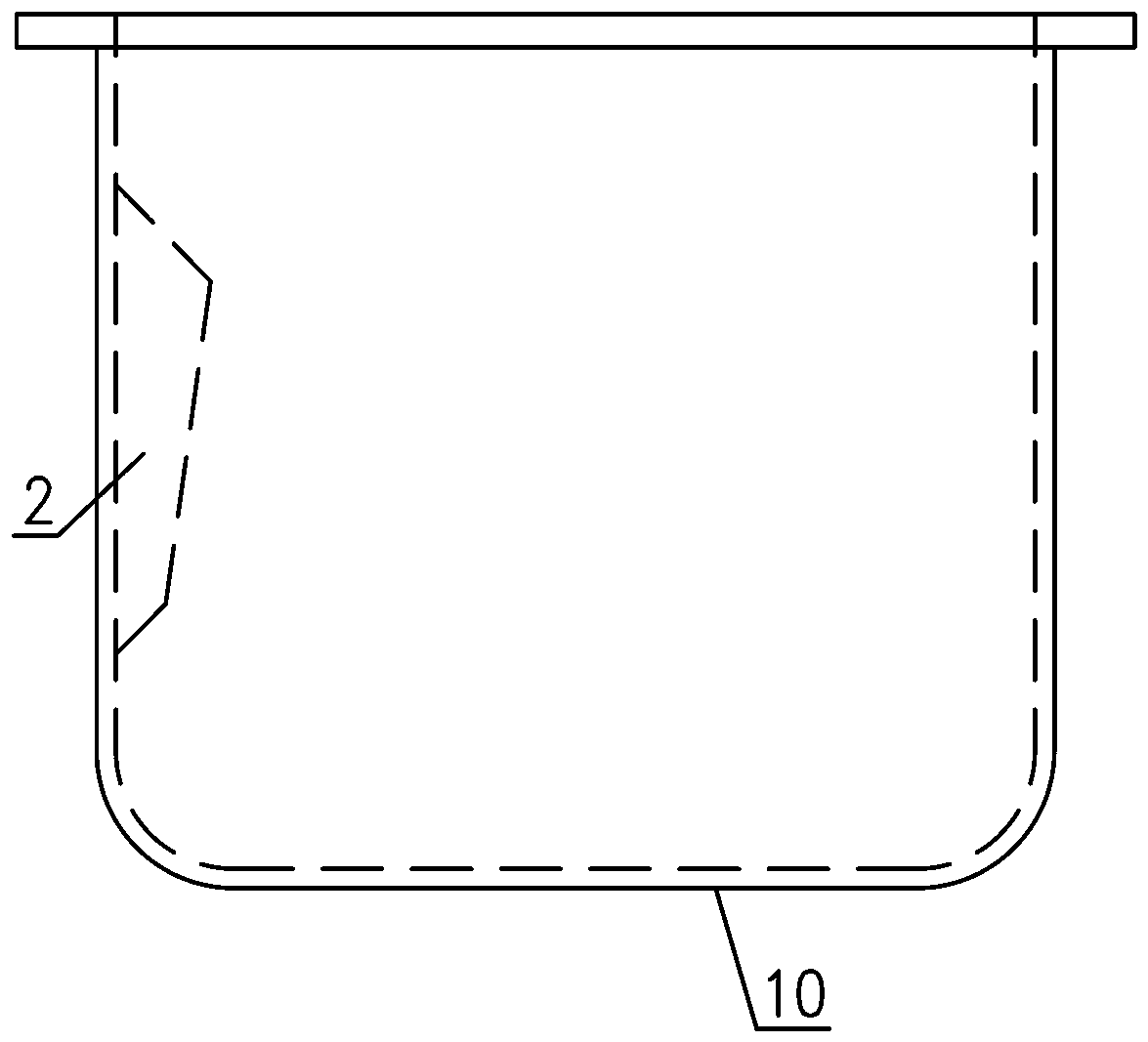
[0022] The mixing baffle guide device is used in the mixing tank, and is fixedly attached to the inner wall of the upper section of the mixing tank when in use. For the convenience of description, here, the inner wall close to the mixing tank is called inward, and the inner wall away from the mixing tank is called outward. Such as figure 1 and Figure 4 As shown, the mixed material baffle guide device described in this embodiment is composed of a fan-shaped upper sealing plate 1, a bent plate 2 and a fan-shaped lower sealing plate 3 to form a whole. The bent plate 2 is a V-shaped plate structure formed by bending the left and right sides around the middle bending line 4 to the inside, and the upper edge of the bent plate 2 forms a V-shaped side with high sides and low middle. , the lower edge of the bent plate 2 forms an inverted V-shaped side with low sides and high middle. The two straight edges of the upper sealing plate 1 are sealed and spliced ​​with the upper edge of ...

Embodiment 2

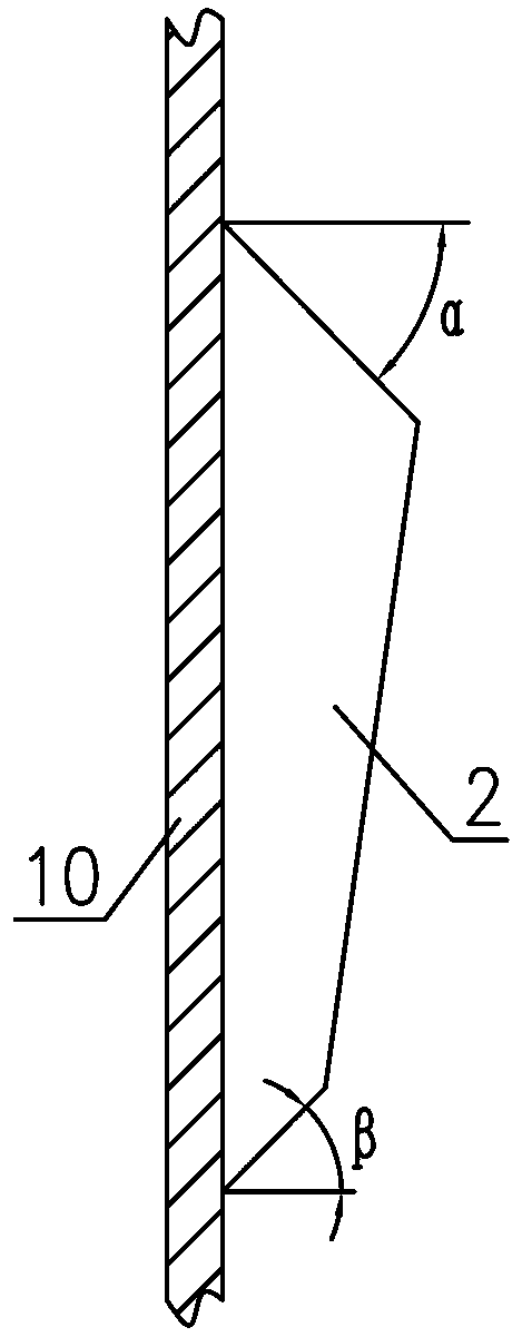
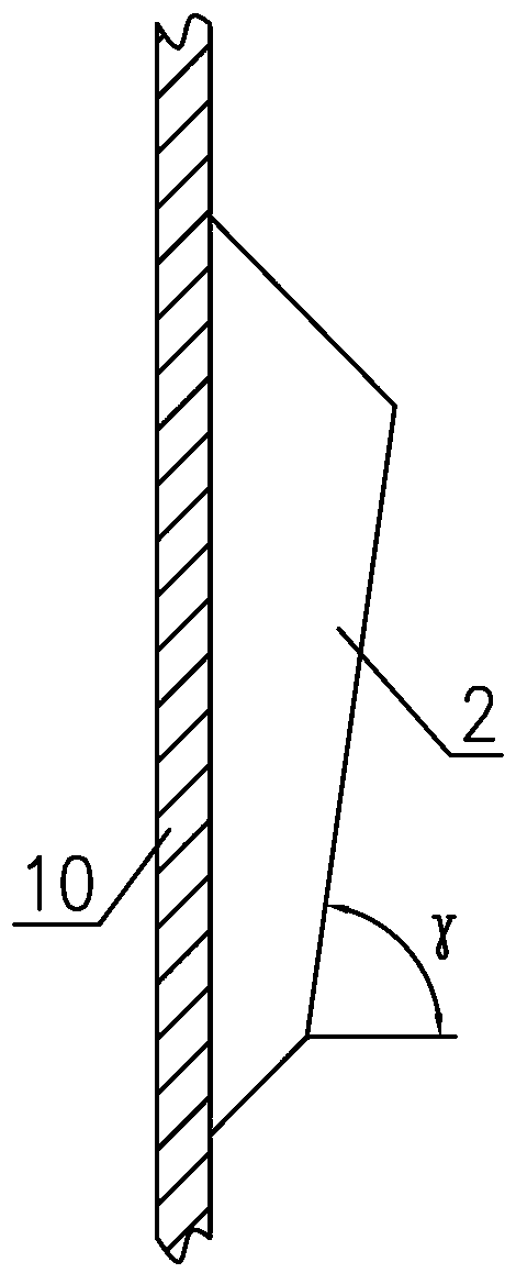
[0024] Such as figure 2 , image 3 and Figure 4 As shown, the difference between this embodiment and Embodiment 1 is that the upper edge of the bent plate 2 forms an asymmetric V-shaped edge with two sides high and the middle part low, and the lower edge of the bent plate 2 forms an asymmetrical V-shaped side with two sides low and the middle part high. Asymmetric inverted V-shaped sides. The angle α between the upper sealing plate 1 and the horizontal plane is 60°-70°, and the angle β between the lower sealing plate 3 and the horizontal plane is 60°-70°.

[0025] The area of ​​the upper sealing plate 1 described in this embodiment is larger than the area of ​​the lower sealing plate 3 , specifically: the area of ​​the upper sealing plate 1 is 1.5 to 2 times that of the lower sealing plate 3 .

[0026] The length of the arc-shaped edge 5 of the upper sealing plate 1 described in this embodiment is greater than the length of the arc-shaped edge 6 of the lower sealing plate...


PUM


Abstract

The invention discloses a mixing, baffling and guiding device. The device is formed by a fan-shaped upper sealing plate, a bent plate and a fan-shaped lower sealing plate, wherein the bent plate is bent inwards from the left and right sides around a middle bending line so as to form a V-shaped plate structure; the upper edge of the bent plate forms a V-shaped edge with high two ends and low middlepart; the lower edge of the bent plate forms an inverted V-shaped edge with two low ends and high middle part; two straight edges of the upper sealing plate are spliced with the upper edge of the bent plate in a sealing manner; two straight edges of the lower sealing plate is spliced with the lower edge of the bent plate in a sealing manner; and when the upper sealing plate, the bent plate and the lower sealing plate are integrally spliced to be adhered on the inner side wall of a mixing barrel, the arc-shaped edge of the upper sealing plate can tightly fit with the inner side wall of the mixing barrel, the arc-shaped edge of the lower sealing plate can tightly fit with the inner side wall of the mixing barrel, the edges of the bent plate at the left and right sides can tightly fit withthe inner side wall of the mixing barrel; and an enclosed cavity is formed among the upper sealing plate, the bent plate, the lower sealing plate and the mixing barrel. The device is capable of enabling materials to be mixed more uniformly.

Description

technical field [0001] The invention relates to the technical field of mixing materials, in particular to a material mixing baffle guide device. Background technique [0002] The rapid development of the plastics, chemical, pharmaceutical, and food industries has led to the rapid development of mixing technology and equipment. In recent years, with the continuous development and application of new technologies, the production efficiency of mixing equipment has generally been rapidly improved. [0003] The automatic batching and mixing production line is mainly used for automatic control in the process of quantitative configuration and mixing of various added components before the molding process of PVC and other materials. It has the characteristics of high degree of automation, precise control, high efficiency, low energy consumption, advanced and reliable performance, etc. According to the function, the production line can be divided into four control units: conveying uni...

Claims


Application Information

Patent Timeline
IPC IPC(8): B01F15/00
CPCB01F35/50B01F35/531
Inventor 刘扣芬陆兵刘卫祥
Owner 苏州联冠机械有限公司
Learn More