A physically catalyzed liquid mixing impeller

A technology of liquid mixing and impeller, which is applied in the direction of fluid mixers, mixers, chemical instruments and methods, etc., can solve the problems of little effect on energy saving and emission reduction, labor cost burden, hidden safety hazards, etc., and achieve novel technology and increase Loss, the effect of improving combustion efficiency

Active Publication Date: 2022-06-07
SANYA JULAN NEW ENERGY DEV
View PDF5 Cites 0 Cited by
  • Summary
  • Abstract
  • Description
  • Claims
  • Application Information

AI Technical Summary

Problems solved by technology

Bring potential risks and burdens to environmental protection, hidden safety hazards, and labor costs
[0006] 3. The cost of producing "mutual solvent" is relatively high, and due to the potential burden, it has little effect on energy saving and emission reduction

Method used


Image

  • A physically catalyzed liquid mixing impeller
  • A physically catalyzed liquid mixing impeller
  • A physically catalyzed liquid mixing impeller

Examples


Embodiment 1

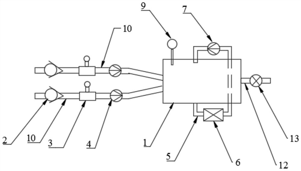
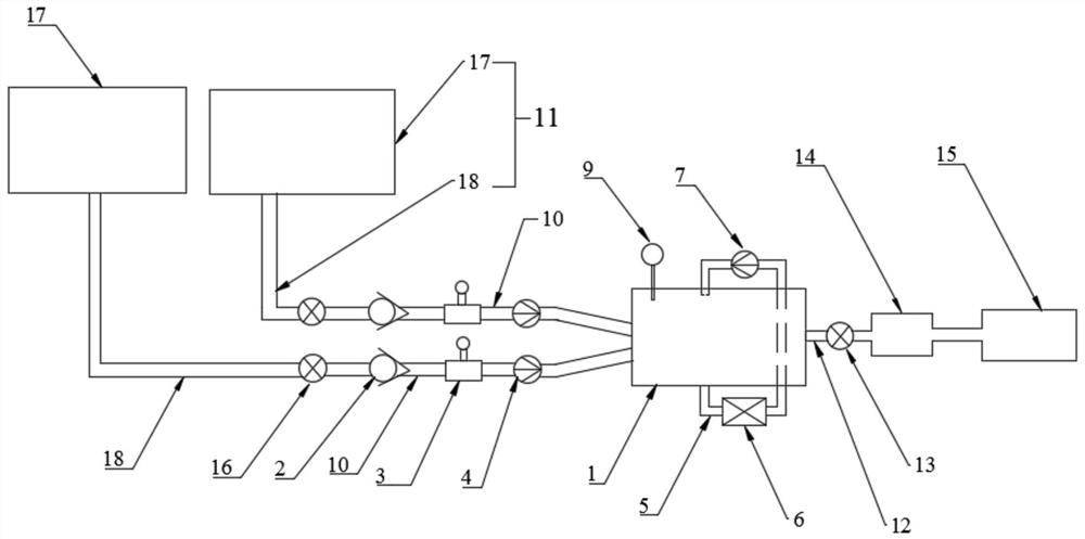
[0031] see Figures 1 to 2 , a physical catalytic liquid mixing propeller, comprising a mixing container 1, one side wall of the mixing container 1 is connected with a plurality of feed pipes 10, in this embodiment, the number of the feed pipes 10 is two One, the other side wall is connected to the burner input pipe 12, the burner input pipe 12 is provided with a first valve 13, and the burner input pipe 12 is used to communicate with the burner 14; One end is used for corresponding connection with a raw material output end 11, the raw material output end 11 includes a raw material storage tank 17 and an output pipeline 18, the output pipeline 18 is provided with a second valve 16, and the raw material output end 11 is used for outputting raw materials; The other end of the pipeline 10 is connected with the mixing container 1; each feeding pipeline 10 is provided with a one-way solenoid valve 2, a flow meter 3 and a first conveying pump 4 in turn; the mixing container 1 is con...

Embodiment 2

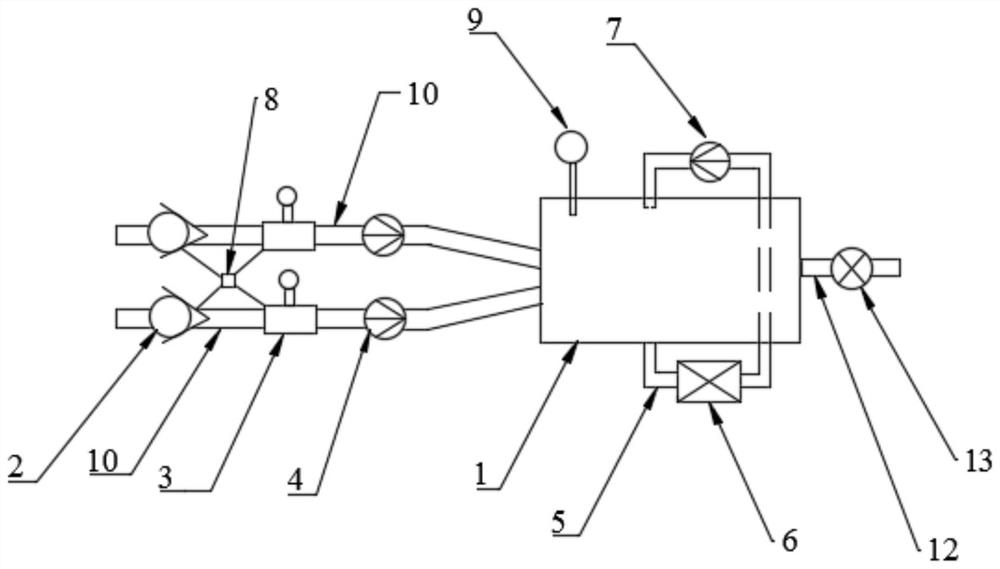
[0035] like Figures 3 to 4 As shown, the difference between this embodiment and Embodiment 1 is that the flow meter 3 is an electronic flow meter 3, and the pusher further includes a PLC controller 8, which is respectively connected with the one-way solenoid valve 2 and the one-way solenoid valve 2 and The electronic flow meter 3 is connected. When in use, the PLC controller 8 presets the target raw material value. When the electronic flow meter 3 detects that the flow reaches the target raw material value, it transmits a signal to the PLC controller 8, and the PLC controller 8 controls the one-way electromagnetic Valve 2 is closed, and the delivery of raw materials is automatically stopped to achieve precise target burning of raw materials.


PUM


Abstract

The invention provides a physically catalyzed liquid mixing propeller, which includes a mixing container, one side wall of the mixing container is connected with a plurality of feed pipes, and the other side wall is connected with a burner input pipe, and the burner input pipe There is a first valve on the feed pipe; one end of the feed pipe is used to connect to the raw material output end, and the other end is connected to the mixing container; the feed pipe is provided with a one-way solenoid valve, a flow meter and a first delivery pump in sequence ; The mixing container is communicated with a circulation pipeline, and the circulation pipeline is provided with a stirring device and a second delivery pump in sequence. The invention adopts multi-channel parallel flow mode, high-speed stirring and pushing, forming a circulating flow, realizing vortex-type high-efficiency mixing in the mixing container, sufficient mutual dissolution, and pushing the mixed dynamic liquid in a very short time under dynamic conditions The combustion chamber achieves the purpose of synergistic combustion, making the fuel use efficiency reach more than 98%, which greatly improves the combustion efficiency.

Description

technical field [0001] The invention relates to the field of auxiliary equipment for fuel delivery, in particular to a physical catalysis liquid mixing propeller. Background technique [0002] The energy liquid fuels generally used for combustion, if there are two or more liquid fuels of different types or different chemical components, almost always use a "mutual solvent" or "additive" as a medium to make the two One or two or more substances do not react, stratify and precipitate with each other, so as to obtain a synergistic effect. However, the relative ratio of the mutually soluble substances is very limited, and the cost of "mutual solvent" is high, the reaction of the mutual dissolution process is slow, and the equipment is complicated. [0003] The original use of "mutual solvent" to complete or incompletely realize the mixed use of two or more substances (liquids) has the following defects: [0004] 1. Most of the components of the "mutual solvent" raw materials a...

Claims


Application Information

Patent Timeline
Patent Type & Authority Patents(China)
IPC IPC(8): B01F25/50B01F35/71B01F35/22F23K5/10F23K5/14
CPCF23K5/10F23K5/147B01F25/52B01F35/2111B01F35/2206B01F35/7164B01F35/7176B01F35/71805B01F2101/501Y02T10/12
Inventor 林敬胜李光栋李颖
Owner SANYA JULAN NEW ENERGY DEV
Why Eureka
Try Eureka