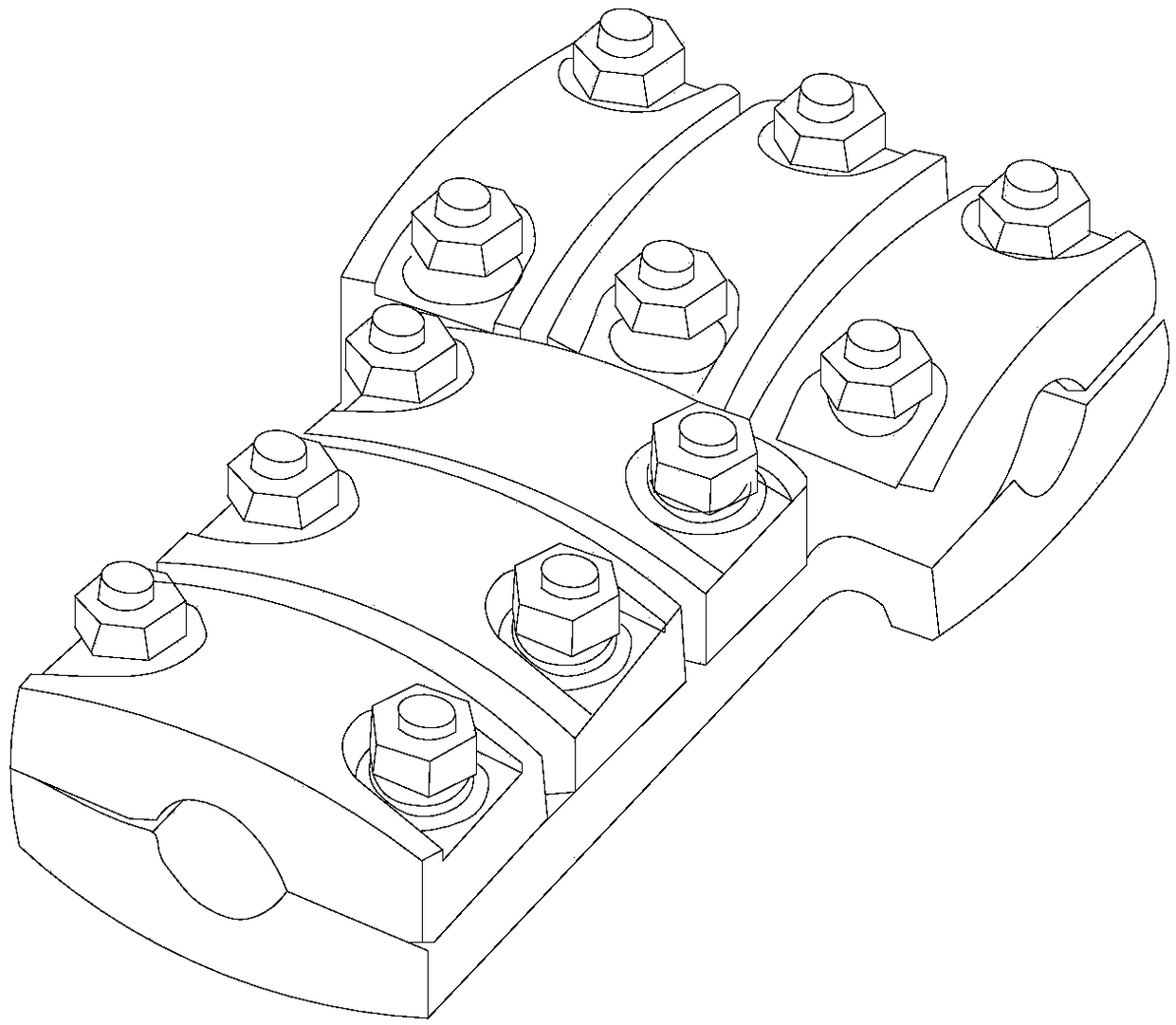
Short-circuit cable clamp with characteristics of quick loading and unloading and short-circuit implementation method thereof
A short-terminal clamp and fast technology, applied in the field of power grid, can solve the problems of shortening the short-terminal operation time, short-terminal short-terminal high-altitude short-circuit time-consuming, threatening the personal safety of operators, etc., to achieve flexible combination and replacement, reduce Threat to personal safety, effect of improving safety factor
- Summary
- Abstract
- Description
- Claims
- Application Information
AI Technical Summary
Problems solved by technology
Method used
Image
Examples
Embodiment 1
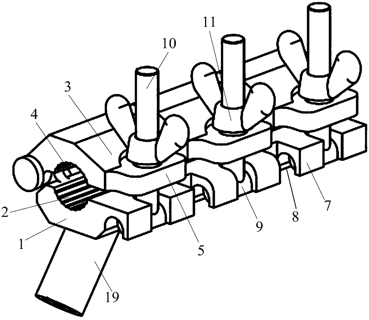
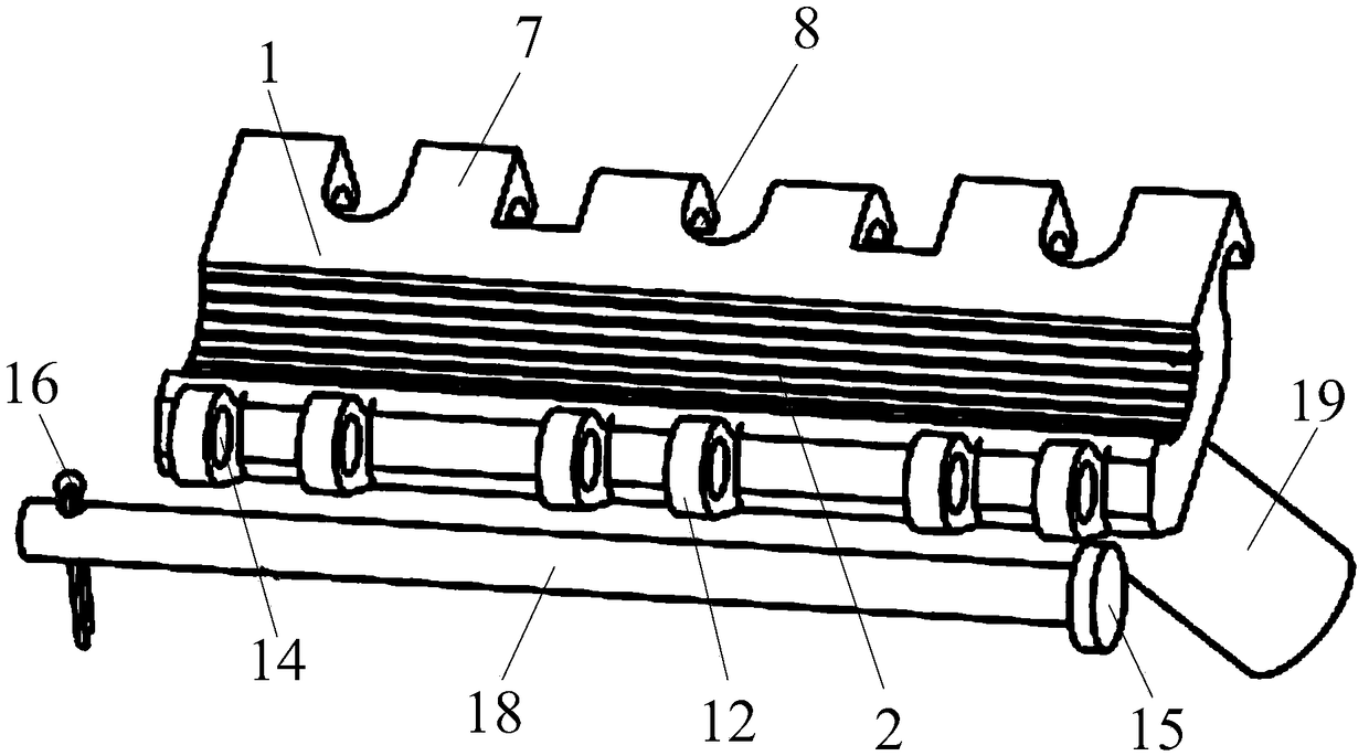
[0033] A quick-release short-terminal clamp, such as Figure 2 to Figure 5 As shown, it includes a bottom cover 1, the first wire groove 2 with both ends open is arranged on the bottom cover 1, and several side-by-side glands 3 are hinged on the bottom cover 1 through the connecting shaft 18, and the surface of the gland 3 is arranged The second wire groove 4 with both ends open, the second wire groove 4 and the first wire groove 2 are facing each other, the long axis of the second wire groove 4 is parallel to the long axis of the first wire groove 2, and the One end of the gland 3 away from the connecting shaft 18 is fixedly connected to the mounting plate 5, the mounting plate 5 is provided with a through hole 6, and the two ends of the mounting plate 5 along the long axis direction of the second wire groove 4 are facing a limit Flange 7, the limit flange 7 is fixedly connected with the bottom cover 1, the side surface of the limit flange 7 facing away from the direction whe...
Embodiment 2
[0036] A quick-loading and dismounting short-terminal clip. On the basis of Embodiment 1, a number of first hinge seats 12 are provided at the end of the bottom cover 1 away from the direction where the limit flange 7 is located. The first hinge seats 12 are connected to the The limit flanges 7 are facing one by one; two second hinge seats 13 are provided at the end of the gland 3 away from the direction where the mounting plate 5 is located, and shaft holes are provided on the first hinge seat 12 and the second hinge seat 13 14 ; the connecting shaft 18 passes through all the shaft holes 14 on the first hinge base 12 and the second hinge base 13 . One end of the connecting shaft 18 is provided with a plug 15 and the other end is provided with a cotter pin 16 . The cross-sections of the first wire groove 2 and the second wire groove 4 are arc-shaped with equal radii. The inner walls of the first wire groove 2 and the second wire groove 4 are provided with anti-slip lines para...
Embodiment 3
[0038] A quick-loading and dismounting short-terminal clamp, as attached Figure 6 As shown, on the basis of any of the above embodiments, the mounting plate 5 is provided with a notch 17 communicating with the through hole 6 , and the notch 17 is located on the side of the mounting plate 5 away from the connecting shaft 18 .
PUM
 Abstract
Description
Claims
Application Information
 - Generate Ideas
- Intellectual Property
- Life Sciences
- Materials
- Tech Scout
- Unparalleled Data Quality
- Higher Quality Content
- 60% Fewer Hallucinations
Browse by: Latest US Patents, China's latest patents, Technical Efficacy Thesaurus, Application Domain, Technology Topic, Popular Technical Reports.
© 2025 PatSnap. All rights reserved.Legal|Privacy policy|Modern Slavery Act Transparency Statement|Sitemap|About US| Contact US: help@patsnap.com


