
A quick loading and unloading short-circuit clamp and its short-circuit method

A short-terminal clip and fast technology, applied in the field of power grid, can solve the problems of short-terminal clip high-altitude short-circuit time-consuming, shorten short-terminal operation time, and threaten the personal safety of operators, so as to achieve flexible combination and replacement, reduce Threat to personal safety, effect of improving safety factor

Active Publication Date: 2020-02-14
国网四川省电力公司技能培训中心 +2
View PDF5 Cites 0 Cited by
  • Summary
  • Abstract
  • Description
  • Claims
  • Application Information

AI Technical Summary

Problems solved by technology

[0003] The purpose of the present invention is to provide a quick-loading and dismounting short-circuit clip and its short-circuiting method, so as to solve the problem of long time-consuming high-altitude short-circuiting of short-circuit clips in the prior art and threaten the personal safety of operators, and to realize shortening of the short-circuit operation. The duration and the purpose of reducing potential safety hazards

Method used


Image

  • A quick loading and unloading short-circuit clamp and its short-circuit method
  • A quick loading and unloading short-circuit clamp and its short-circuit method
  • A quick loading and unloading short-circuit clamp and its short-circuit method

Examples


Embodiment 1

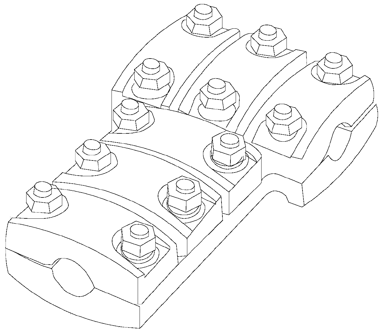
[0033] A quick-release short-terminal clamp, such as Figure 2 to Figure 5 As shown, it includes a bottom cover 1, the first wire groove 2 with both ends open is arranged on the bottom cover 1, and several side-by-side glands 3 are hinged on the bottom cover 1 through the connecting shaft 18, and the surface of the gland 3 is arranged The second wire groove 4 with both ends open, the second wire groove 4 and the first wire groove 2 are facing each other, the long axis of the second wire groove 4 is parallel to the long axis of the first wire groove 2, and the One end of the gland 3 away from the connecting shaft 18 is fixedly connected to the mounting plate 5, the mounting plate 5 is provided with a through hole 6, and the two ends of the mounting plate 5 along the long axis direction of the second wire groove 4 are facing a limit Flange 7, the limit flange 7 is fixedly connected with the bottom cover 1, the side surface of the limit flange 7 facing away from the direction whe...

Embodiment 2

[0036] A quick-loading and dismounting short-terminal clip. On the basis of Embodiment 1, a number of first hinge seats 12 are provided at the end of the bottom cover 1 away from the direction where the limit flange 7 is located. The first hinge seats 12 are connected to the The limit flanges 7 are facing one by one; two second hinge seats 13 are provided at the end of the gland 3 away from the direction where the mounting plate 5 is located, and shaft holes are provided on the first hinge seat 12 and the second hinge seat 13 14 ; the connecting shaft 18 passes through all the shaft holes 14 on the first hinge base 12 and the second hinge base 13 . One end of the connecting shaft 18 is provided with a plug 15 and the other end is provided with a cotter pin 16 . The cross-sections of the first wire groove 2 and the second wire groove 4 are arc-shaped with equal radii. The inner walls of the first wire groove 2 and the second wire groove 4 are provided with anti-slip lines para...

Embodiment 3

[0038] A quick-loading and dismounting short-terminal clamp, as attached Figure 6 As shown, on the basis of any of the above embodiments, the mounting plate 5 is provided with a notch 17 communicating with the through hole 6 , and the notch 17 is located on the side of the mounting plate 5 away from the connecting shaft 18 .


PUM


Abstract

The invention discloses a short-circuit cable clamp with characteristics of quick loading and unloading and a short-circuit implementation method thereof. A first wire slot with two open ends is formed in a bottom cover; and a plurality of glands arranged side by side are hinged to the bottom cover by a connecting shaft. A second wire slot with two open ends is formed in the surface of each gland.A mounting plate is fixedly connected to one end, away from the connecting shaft, of each gland; a through hole is formed in each mounting plate; the two ends of the mounting plates along the long axis directions of the second wire slots face limiting flanges respectively; the limiting flanges are fixedly connected with the bottom cover; and arc grooves with two open ends are formed in the surfaces of sides, deviating from the directions of the mounting plates, of the limiting flanges. In addition, connecting elements include limiting shaft rods, locking screw rods, and nuts; the two ends ofeach limiting shaft rod are arranged in the arc grooves of every two limiting flanges facing one mounting plate; the locking screw rods are fixed at the limiting shaft rods; and the nuts sleeve the locking screw rods. Therefore, a problem of long time consumed by high-altitude short circuit of the short-circuit cable clamp in the prior art is solved; and thus objectives of shortening the short-circuit connection working time and reducing the potential safety hazard are achieved.

Description

technical field [0001] The invention relates to the field of power grids, in particular to a quick-loading and dismounting short-circuit clip and a short-circuit method thereof. Background technique [0002] In recent years, with the intensification of climate change and the increase of extreme weather, the 110kV ~ 500kV power lines are very easy to be overloaded in winter and summer. Overloading the line will cause the connector to heat up or even burn out. Therefore, hot treatment of hot joints is one of the most common maintenance tasks in power systems. In order to ensure the normal power supply during the replacement of the connector, it is necessary to connect a bypass with a short-circuit wire at both ends of the connector to allow the current to flow through the short-circuit wire. This is the short-circuit wiring operation in the power industry. In the prior art, it is common to use such as attached figure 1 The stud-type T-clip shown is used as a short-terminal ...

Claims


Application Information

Patent Timeline
Patent Type & Authority Patents(China)
IPC IPC(8): H01R25/16
CPCH01R25/162H01R25/164
Inventor 杜印官魏欣郑和平陈楠陈立覃浩隆茂胡永银张珂王磊
Owner 国网四川省电力公司技能培训中心
Learn More