Slow wave structure suitable for dual-sheet backward wave oscillator

A technology of slow wave structure and wave oscillation, applied in the field of slow wave structure, can solve the complex processing and complex problems of slow wave structure, and achieve the effect of simple structure, high power output and interaction efficiency, and good heat dissipation

Active Publication Date: 2019-01-01
UNIV OF ELECTRONICS SCI & TECH OF CHINA
View PDF7 Cites 7 Cited by
  • Summary
  • Abstract
  • Description
  • Claims
  • Application Information

AI Technical Summary

Problems solved by technology

However, this method of improving the working performance of the tube often makes the slow-wave

Method used


Image

  • Slow wave structure suitable for dual-sheet backward wave oscillator
  • Slow wave structure suitable for dual-sheet backward wave oscillator
  • Slow wave structure suitable for dual-sheet backward wave oscillator

Examples


Embodiment

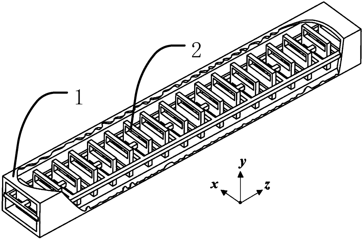
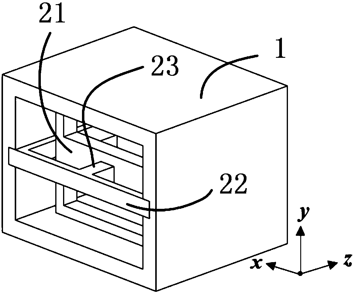
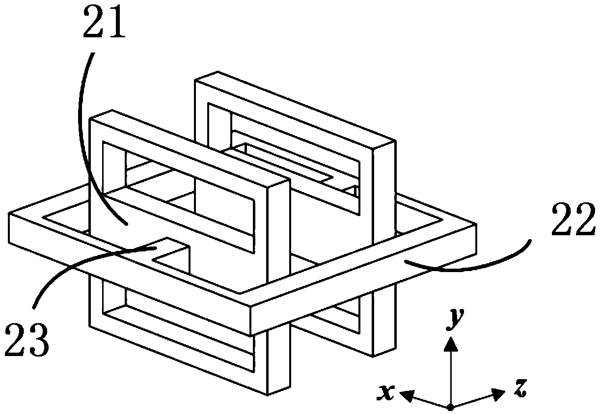
[0027] figure 1 It is a structural diagram of a specific embodiment of the present invention applicable to the slow-wave structure of the dual-ribbon injection back-wave oscillator. In order to better demonstrate the internal structure of the present invention, figure 1 Part of the rectangular waveguide is hidden in . Such as figure 1 As shown, the slow-wave structure applicable to the double-ribbon injector return wave oscillator of the present invention includes a rectangular waveguide 1 and several vertical metal plate pair structures 2, and the present invention is a periodic structure. figure 2 It is a single-period structure diagram of the slow-wave structure applicable to the double-band injection back-wave oscillator of the present invention.

[0028] The rectangular waveguide 1 is a commonly used technology in the microwave field, and is not the technical focus of the present invention, so it will not be described in detail here. Next, the structure 2 of the verti...


PUM


Abstract

The present invention discloses a slow wave structure suitable for a dual-sheet backward wave oscillator. The structure comprises a rectangular waveguide and a plurality of vertical metal panel pair structures, each vertical metal panel pair structure comprises a pair of vertical rectangular metal panels, one rectangular metal frame and a pair of metal strips, the upper and lower half portions ofthe vertical rectangular metal panels are respectively provided with rectangular holes, the two vertical rectangular metal panels are arranged at the internal portions of the rectangular metal framesin parallel, and the two metal strips are configured to respectively connect with vertical rectangular metal panels and the rectangular metal frames; and the rectangular metal frames in the vertical metal panel pair structures are connected in order to take as an integration inserted into the rectangular waveguide to form a slow wave structure. The slow wave structure suitable for a dual-sheet backward wave oscillator is high in output power and electron efficiency.

Description

technical field [0001] The invention belongs to the field of microwave electric vacuum technology, and more specifically relates to a slow wave structure suitable for a double-strip injector return wave oscillator. Background technique [0002] A microwave vacuum device is a device that uses charged particles to oscillate or amplify microwave signals in a vacuum environment. One of the biggest features of this device is that it can generate high power output, which makes microwave electric vacuum devices play an important role in the fields of electronic countermeasures, electronic countermeasures, and satellite communications. The rapid development of solid-state devices and the urgent needs of aerospace and military fields have brought challenges and opportunities to electric vacuum devices. The new generation of electric vacuum devices requires not only high power and high performance, but also high reliability, mass production and low manufacturing cost, so as to meet n...

Claims


Application Information

Patent Timeline
IPC IPC(8): H01J23/24
CPCH01J23/24
Inventor 吴钢雄魏彦玉杨睿超李倩雷霞方栓柱岳玲娜殷海荣徐进赵国庆王文祥
Owner UNIV OF ELECTRONICS SCI & TECH OF CHINA
Why Eureka
Try Eureka