
Radar speedometer with damping function and damping method

A radar speedometer and functional technology, applied in the field of radar speedometer and shock absorption, can solve problems such as poor shock absorption effect, increased construction volume, hidden safety hazards, etc., to increase buffering and absorption capacity, ensure normal work, and improve effective The effect of protection

Inactive Publication Date: 2019-01-01
李汝和
View PDF0 Cites 0 Cited by
  • Summary
  • Abstract
  • Description
  • Claims
  • Application Information

AI Technical Summary

Problems solved by technology

This type of speedometer generally needs to be powered by a cable, which increases the amount of construction during the installation process, and there are certain safety hazards, and most of the current radar speedometers do not have a shock absorption function, resulting in a poor shock absorption effect , which in turn affects the quality of the image picture obtained by the camera device. In addition, some existing speedometers equipped with shock absorbing devices have a relatively simple structure, and the anti-seismic direction is relatively single, and it is impossible to realize all-round shock resistance and shock absorption for the speedometer. , does not have a good buffer effect

Method used


Image

  • Radar speedometer with damping function and damping method
  • Radar speedometer with damping function and damping method
  • Radar speedometer with damping function and damping method

Examples


Embodiment Construction

[0025] The following will clearly and completely describe the technical solutions in the embodiments of the present invention with reference to the accompanying drawings in the embodiments of the present invention. Obviously, the described embodiments are only some, not all, embodiments of the present invention. Based on the embodiments of the present invention, all other embodiments obtained by persons of ordinary skill in the art without making creative efforts belong to the protection scope of the present invention.

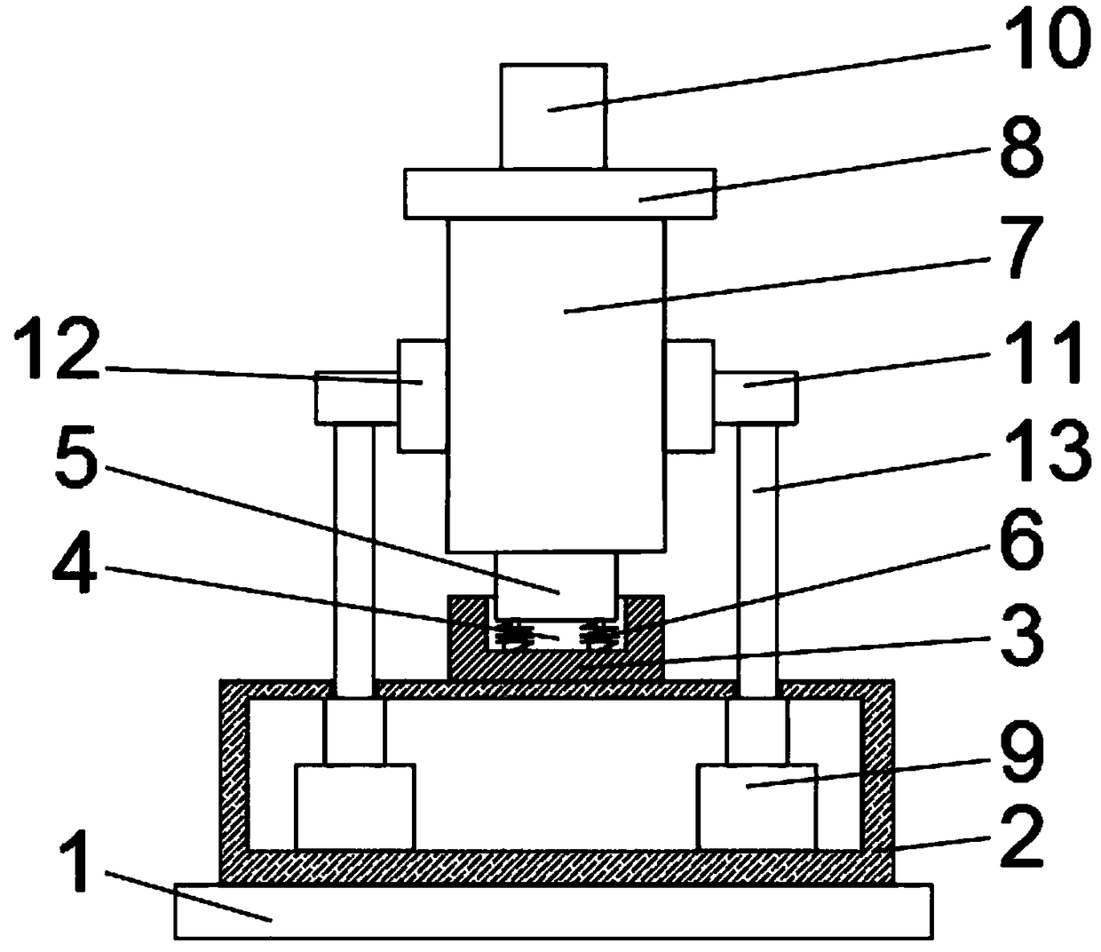
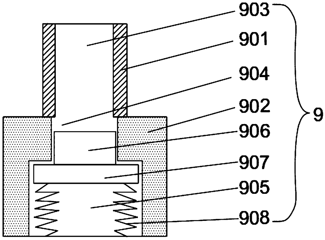
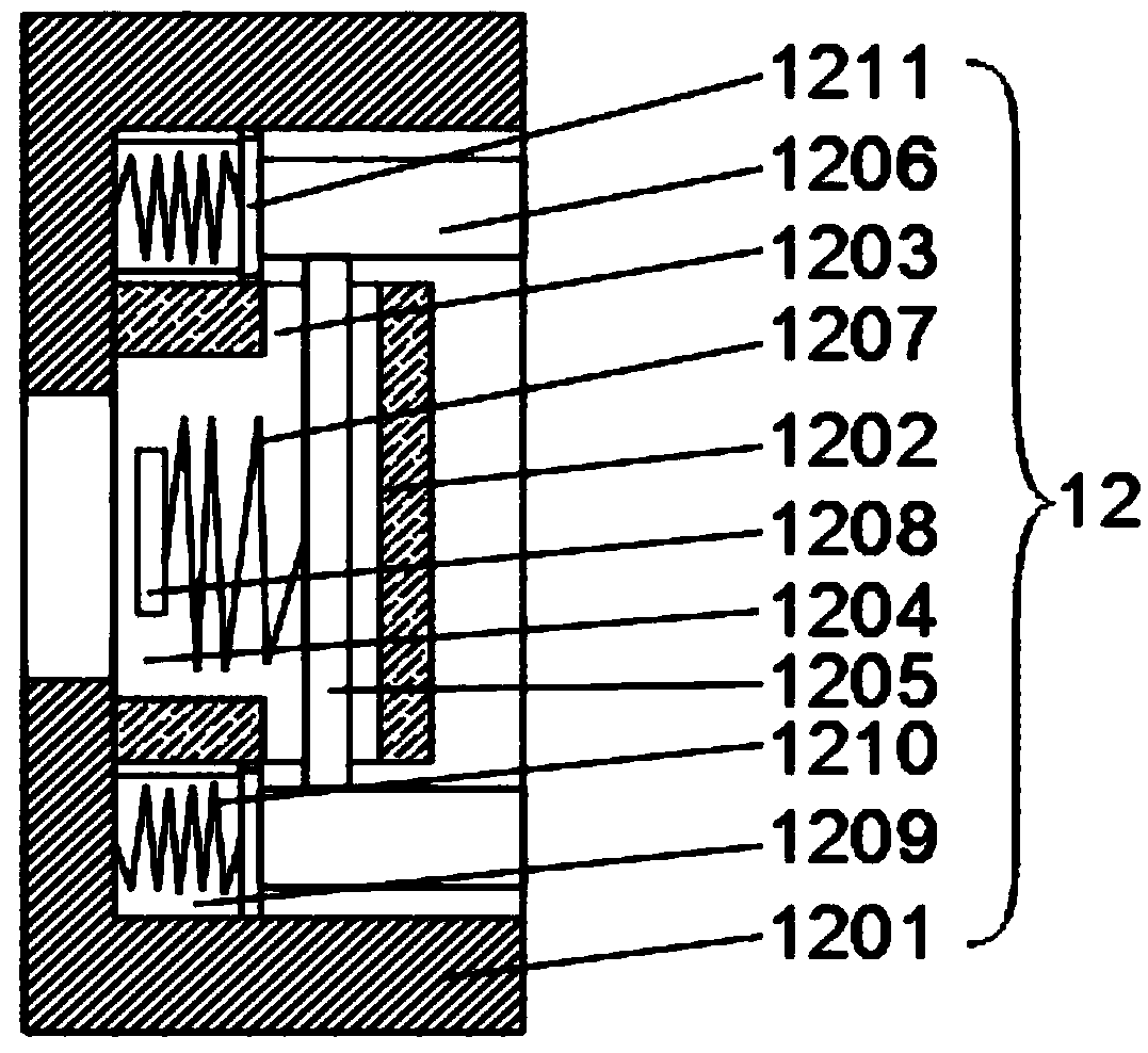
[0026] see Figure 1-4 , the present invention provides a technical solution: a radar speedometer with a shock-absorbing function, including a base 1, a protection box 2 is arranged on the top of the base 1, a support seat 3 is provided at the center of the top of the protection box 2, and the support seat 3 There is a buffer cavity 4 on the top of the buffer cavity 4, and a support block 5 is nested in the buffer cavity 4. Two sets of spring rods 6 with the s...


PUM


Abstract

The invention discloses a radar speedometer with a damping function in the radar speed measuring anti-seismic and shock absorption technology field. The center of the top of a protection box is provided with a support seat. The top of the support seat is provided with a buffer cavity. A support block is nested in the buffer cavity. The left and right sides of the bottom of the support block are provided with two groups of spring rod with a same structure. The top of a support frame is provided with a buffer plate. The top of the buffer plate is provided with a speedometer. The left and right side walls of the support frame are provided with second buffer devices. One side wall of each second buffer device, which is far away from the support frame, is nested with a support plate. The bottomof the support plate is provided with a support rod. The bottom end of the support rod passes through the top of the protection box and then is extended into a first buffer device. The vibration of avehicle passing a road surface next to the installation position of the speedometer can be effectively absorbed so that an influence on the speedometer can be reduced, and the accuracy of the speed measurement of the passing vehicle by the speedometer is increased.

Description

technical field [0001] The invention relates to the technical field of radar speed measurement, shock resistance and shock absorption, in particular to a radar speed measurement instrument with a shock absorption function and a shock absorption method. Background technique [0002] In the prior art, commonly used speedometers include laser speedometers, radar speedometers, strobe speedometers and the like. This type of speedometer generally needs to be powered by a cable, which increases the amount of construction during the installation process, and there are certain safety hazards, and most of the current radar speedometers do not have a shock absorption function, resulting in a poor shock absorption effect , which in turn affects the quality of the image picture obtained by the camera device. In addition, some existing speedometers equipped with shock absorbing devices have a relatively simple structure, and the anti-seismic direction is relatively single, and it is impos...

Claims


Application Information

Patent Timeline
IPC IPC(8): G01S13/58G01S7/02
CPCG01S13/58G01S7/02
Inventor 钟焕雄
Owner 李汝和
Learn More