
Knitting Element Carrier

A technology of knitting elements and elements, which is applied in the field of knitting element carriers, can solve problems such as high noise, and achieve high longitudinal stiffness and reliable length changes

Active Publication Date: 2020-08-14
KARL MAYER STOLL R&D GMBH
View PDF3 Cites 0 Cited by
  • Summary
  • Abstract
  • Description
  • Claims
  • Application Information

AI Technical Summary

Problems solved by technology

However the high working speed also causes high noise levels when running the machine

Method used


Image

  • Knitting Element Carrier
  • Knitting Element Carrier
  • Knitting Element Carrier

Examples


Embodiment Construction

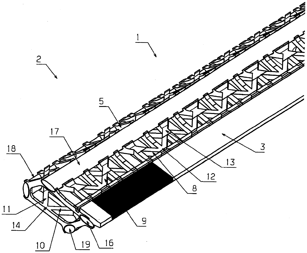
[0036] exist figure 1 and 2 The knitted element carrier 1 shown schematically in FIG. 1 has a main body 2 and a knitted element receptacle 3 . The body 2 is constructed as a skeletal structure, that is to say it has a large number of body bars 4-11. The body rods are connected to each other at nodes 12-15. The main body rods thus form a frame building-like structure so to speak.

[0037] Fiber-reinforced plastic rods 16-19 are attached to the skeleton structure. The plastic rods 16-19 are preferably formed from unidirectional fiber reinforced plastic (CFK) as pultruded rods. The plastic rods have a very high longitudinal stiffness and in practice have no significant thermal expansion in the longitudinal direction. The length of the plastic rods 16 - 19 preferably corresponds to the overall length of the braided element carrier 1 . However, it can also be provided that at least one of the plastic rods 16 - 19 is divided in the longitudinal direction and is thus provided w...


PUM


Abstract

The present invention relates to a warp knitting tool bar (1). The warp knitting tool bar (1) has a main body (2) and a warp knitting holding portion (3), the main body has a vertical direction. The high operation speed of a warp knitting machine is achieved through a proper cost mode. The main body (2) has a skeleton structure, the skeleton structure is provided with a lots of main body bars (4-11), and the lots of main body bars are connected at the nodes (12-15).

Description

technical field [0001] The present invention relates to a knit element carrier having a main body and a knit element receptacle, the main body having a longitudinal direction. Background technique [0002] Such knitting element carriers are used in warp knitting machines in order to carry knitting tools or knitting elements. [0003] The same type of knitting elements must also be moved homogeneously during the production of the knitted fabric. Knit element carriers, often also referred to as "bars", are used for this. The knitting element is arranged in the knitting element receptacle here. [0004] The knit element carrier must be accelerated and braked typically in one direction at a time and then in the opposite direction during loop formation. Movement transverse to a direction is also added to movement in a direction in some knit element carriers. It is therefore an effort to keep the mass of the knitted element carrier as low as possible. [0005] Warp knitting m...

Claims


Application Information

Patent Timeline
Patent Type & Authority Patents(China)
IPC IPC(8): D04B27/00
CPCD04B27/00D04B27/06D04B27/24
Inventor T.格伦德曼K.科莱克T.巴克M.霍佩M.肖尔莱默F.哈梅林
Owner KARL MAYER STOLL R&D GMBH
Learn More