Seat device
A seat and seat board technology, which is applied in the field of seats, can solve the problems of inconvenient use, troublesome operation, and easy bumping of users, etc.
- Summary
- Abstract
- Description
- Claims
- Application Information
AI Technical Summary
Problems solved by technology
Method used
Image
Examples
Embodiment 1
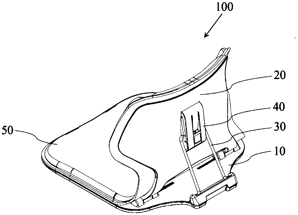
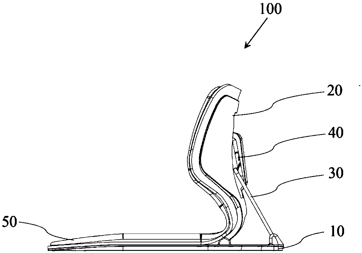
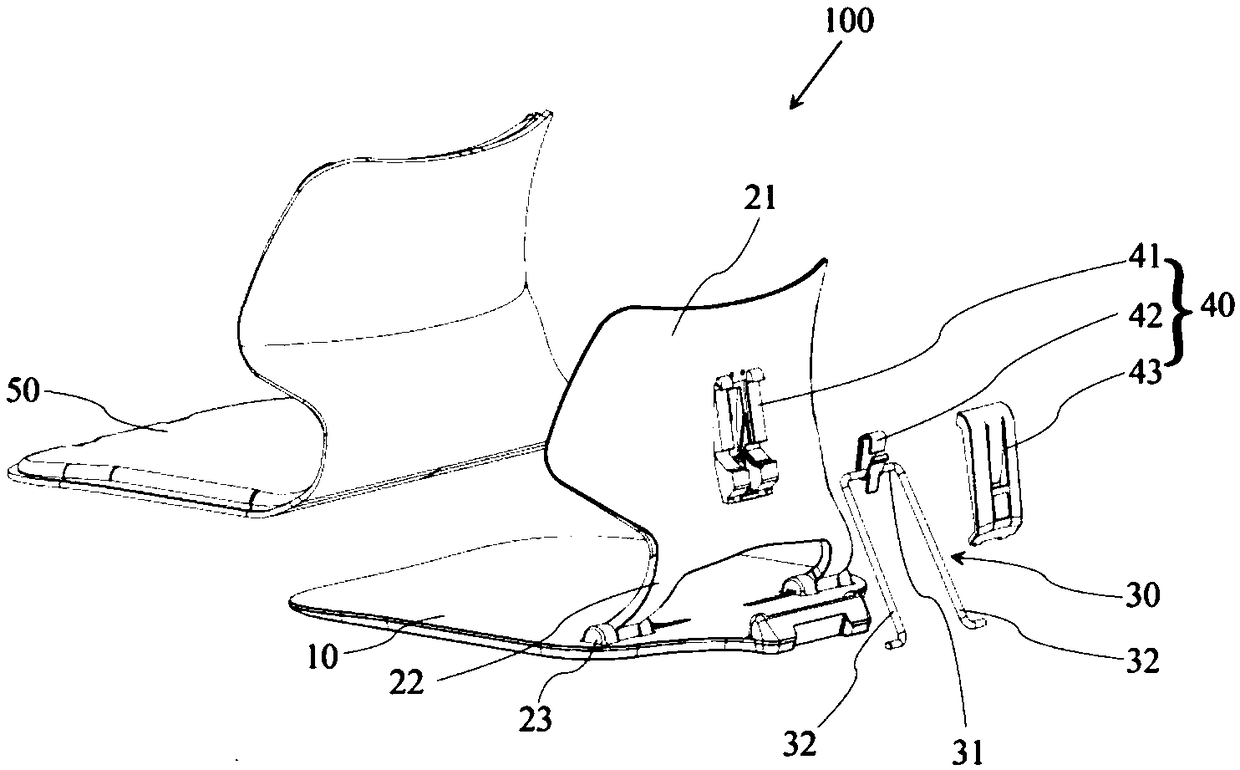
[0044] figure 1 It is a structural schematic diagram of a seat in Embodiment 1 of the present invention, figure 2 It is a schematic diagram of the side view structure of the seat in Embodiment 1 of the present invention, image 3 It is a schematic diagram of the exploded structure of the seat in Embodiment 1 of the present invention.
[0045] Such as figure 1 , figure 2 and image 3 As shown, the seat 100 according to the first embodiment of the present invention includes a seat board 10 , a waist board 20 , a support member 30 , a movement path control assembly 40 and a seat surface 50 .
[0046] The seat board 10 is plate-shaped, corresponding to the user's buttocks, and supports the user's buttocks during use. In addition, the lower surface of the seat board 10 is a plane, and the seat board 10 can be placed on other seats with supporting legs during use, so as to be used in conjunction with such seats.
[0047] The waist board 20 corresponds to the waist of the use...
Embodiment 2
[0112] In the second embodiment, the same structures as those in the first embodiment are assigned the same symbols and the same descriptions are omitted.
[0113] Figure 14 It is a structural schematic diagram of a seat in Embodiment 2 of the present invention. exist Figure 14 In , some detailed structures are omitted in order to briefly show the overall structure of the seat.
[0114] Such as Figure 14 As shown, the same as the first embodiment, the seat 200 of this embodiment also has a seat board 10, a waist board 20, a support member 30, a movement path control assembly 40 and a seat surface (not shown in the figure).
[0115] The difference from Embodiment 1 is that the support member 30 of this embodiment is rotatably mounted on the waist board 20, while the movement path control assembly 40 is arranged on the seat board 10, and correspondingly, the support cross bar portion 31 is also located on the support member The lower end of 30 is combined with the seat bo...
Embodiment 3
[0119] In the third embodiment, the same structures as those in the first embodiment are assigned the same symbols and the same explanations are omitted.
[0120] Figure 15 It is a structural schematic diagram of the path adjustment member and the cover member in Embodiment 3 of the present invention.
[0121] Such as Figure 15 As shown, the difference between the seat in this embodiment and the seat 100 in Embodiment 1 is that the accommodating portion 421 of the path adjusting member 42 is a closed ring. That is to say, the first free end 4211 and the second free end 4212 are connected to each other as a whole.
[0122] The above-mentioned structure of this embodiment can also realize the same functions as the cooperation between the pressing piece and the receiving part and the mutual cooperation of the blocks as in the first embodiment, but compared with the first embodiment, since the first free end of the first block 424 is provided 4211 does not exist, and the pres...
PUM
 Abstract
Description
Claims
Application Information
 - R&D
- Intellectual Property
- Life Sciences
- Materials
- Tech Scout
- Unparalleled Data Quality
- Higher Quality Content
- 60% Fewer Hallucinations
Browse by: Latest US Patents, China's latest patents, Technical Efficacy Thesaurus, Application Domain, Technology Topic, Popular Technical Reports.
© 2025 PatSnap. All rights reserved.Legal|Privacy policy|Modern Slavery Act Transparency Statement|Sitemap|About US| Contact US: help@patsnap.com


