Electric motor rotor, electric motor and direct current variable frequency compressor

A motor and rotor technology, which is applied in the fields of motor rotors, motors and DC variable frequency compressors, can solve the problems of difficulty in designing the optimal pole arc coefficient and the limitation of the mechanical strength of the magnetic isolation magnetic bridge, so as to reduce the no-load back electromotive force harmonics. Distortion rate, reduce noise and vibration, and improve the effect of controllability

Pending Publication Date: 2018-12-28
SHANGHAI HITACHI ELECTRICAL APPLIANCES CO LTD
View PDF0 Cites 3 Cited by
  • Summary
  • Abstract
  • Description
  • Claims
  • Application Information

AI Technical Summary

Problems solved by technology

The existing permanent magnet synchronous motors for DC inverter compressors generally use embedded rotors, and the structure of the rotor core 100 is as follows: figure 1 As shown, by designing an appropriate length L of the magnetic isolation slot 101 on the rotor core 100 to optimize the pole arc coefficient, the no-load back EMF harmonics, cogging torque and torque ripple of the motor can be reduced, thereby improving the controllability and performance of the motor. Noise and vibration, the distance between the magnetic isolation groove 101 and the edge of the rotor core 100 forms a magnetic isolation magnetic bridge, W is the width of the magnetic isolation magnetic bridge, but for a rotor with a large outer diameter and a large amount of magnets, the setting of the pole arc coefficient The fixed range is easily limited by the mechanical strength of the magnetic isolation bridge, which makes it difficult to design the optimal pole arc coefficient

Method used


Image

  • Electric motor rotor, electric motor and direct current variable frequency compressor
  • Electric motor rotor, electric motor and direct current variable frequency compressor
  • Electric motor rotor, electric motor and direct current variable frequency compressor

Examples


Embodiment 1

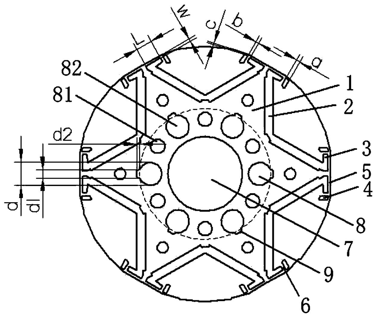
[0022] This embodiment provides a motor rotor, the rotor core 1 of the motor rotor includes rotor punches of the same shape, and the rotor punches are composed of the rotor punches through riveting or welding. figure 2 In the structure shown, the rotor core 1 is provided with a magnet slot 2, a magnetic isolation slot 3 and a magnetic flux arrangement slot 4, the magnet slot 2 is used for embedded and fixed installation of permanent magnets, and the magnetic isolation slot 3 is connected to At the end of the magnet slot 2 close to the edge of the rotor core 1, there is a magnetic isolation bridge 5 between the magnetic isolation slot 3 and the edge of the rotor core 1, and the magnetic flux finishing slot 4 is arranged in parallel One side of the magnetic isolation slot 3 is close to the edge of the rotor core, and the magnetic flux arrangement slot 4 is spaced from the magnetic isolation slot 3 to form a magnetic bridge 6, the magnetic flux arrangement slot 4 and the The dis...

Embodiment 2

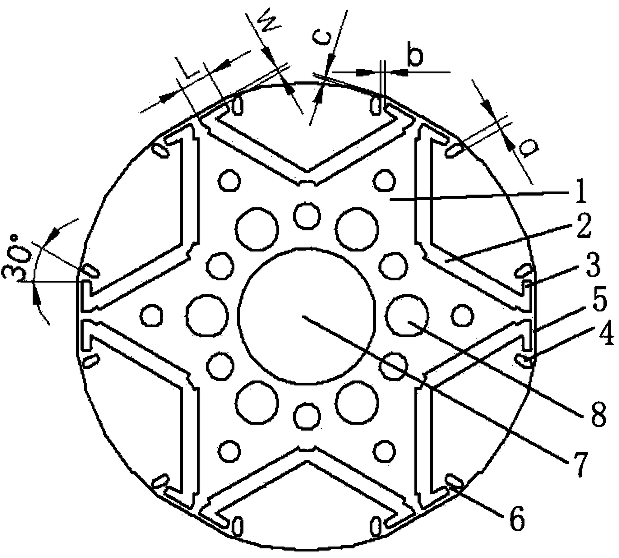
[0033] This embodiment provides a motor rotor, the rotor core 1 of the motor rotor includes rotor punches of the same shape, and the rotor punches are composed of the rotor punches through riveting or welding. image 3 In the structure shown, the rotor core 1 is provided with a magnet slot 2, a magnetic isolation slot 3 and a magnetic flux arrangement slot 4, the magnet slot 2 is used for embedded and fixed installation of permanent magnets, and the magnetic isolation slot 3 is connected to At the end of the magnet slot 2 close to the edge of the rotor core 1, there is a magnetic isolation bridge 5 between the magnetic isolation slot 3 and the edge of the rotor core 1, and the magnetic flux finishing slot 4 is arranged on the One side of the magnetic isolation slot 3 is close to the edge of the rotor core, and an acute angle is formed between the magnetic flux arrangement slot 4 and the magnetic isolation slot 3, and the distance between the magnetic flux arrangement slot 4 and...


PUM


Abstract

An electric motor rotor, an electric motor, and a direct current variable frequency compressor are provided. A magnetic beam finishing groove is added on the rotor core of the electric motor rotor, sothat a magnetic bridge is formed between the magnetic beam finishing groove and the magnetic isolation groove, and the distance between the magnetic beam finishing groove and the magnetic isolation groove causes the magnetic bridge to be magnetically saturated, and then the magnetoresistance increases significantly, close to air magnetoresistance. According to the principle of minimum magnetoresistance, that is, the flux is always closed along the path with the smallest magnetoresistance, magnetic lines of force will be confined to the magnetic bridge. At this time, the magnetoresistances ofthe magnetic beam finishing groove, the magnetic bridge, and magnetic isolation grooves are equivalent, which co-determine the polar arc coefficient, so that on the basis of ensuring the mechanical strength of the magnetic isolation bridge between the magnetic isolation groove and the edge of the rotor core, the pole arc coefficient can be set in a larger range, the optimal pole arc coefficient can be designed, and the optimal pole arc coefficient can be obtained, the harmonic distortion rate of the no-load back electromotive force, the tooth groove torque and the torque ripple can be reduced,the motor control ability is improved, and the motor noise vibration is reduced.

Description

technical field [0001] The invention relates to the technical field of motors and DC frequency conversion compressors, in particular to a motor rotor, a motor and a DC frequency conversion compressor. Background technique [0002] Compressors are the core components of air conditioners, refrigerators and other electrical appliances, and most compressors are driven by electric motors, which have a large amount of energy consumption. With the progress of society and the increasingly severe energy situation, related industries are increasingly committed to launching some energy-saving and consumption-reducing products. In recent years, DC frequency conversion technology has become one of the main technologies in the refrigeration industry. At the same time, permanent magnet synchronous motors have also become the first choice for motors used in compressors. [0003] The permanent magnet synchronous motor for DC inverter compressor is composed of a stator and a rotor. The stato...

Claims


Application Information

Patent Timeline
Patent Type & Authority Applications(China)
IPC IPC(8): H02K1/27H02K1/32
CPCH02K1/2706H02K1/32H02K2213/03
Inventor 范杰张兴志汪圣原孙建龙
Owner SHANGHAI HITACHI ELECTRICAL APPLIANCES CO LTD
Why Eureka
Try Eureka