
Antenna, manufacturing method thereof, and electronic device

An electronic equipment and antenna technology, applied in antennas, antenna parts, antenna supports/mounting devices, etc., can solve the problems of motherboard layout influence, metal integrated mobile phone space occupation, large space occupation, etc., to achieve signal reception and transmission Good ability, enhanced market competitiveness, high complexity effect

Inactive Publication Date: 2018-12-28
GUANGDONG OPPO MOBILE TELECOMM CORP LTD
View PDF11 Cites 2 Cited by
  • Summary
  • Abstract
  • Description
  • Claims
  • Application Information

AI Technical Summary

Problems solved by technology

[0003] Among them, the first two methods generally make the antenna directly on the middle frame or back cover of the mobile phone, which will take up a lot of space and thus have a certain impact on the layout of the motherboard.
Moreover, especially for 5G antennas, the middle frame of a metal integrated mobile phone cannot lay out 5G antennas
Moreover, the space of the metal integrated mobile phone is basically occupied by the line of the mobile phone antenna, leaving very limited space for the near field communication (NFC) antenna and circuit.
Therefore, the current method of making antennas still needs to be improved

Method used


Image

  • Antenna, manufacturing method thereof, and electronic device
  • Antenna, manufacturing method thereof, and electronic device
  • Antenna, manufacturing method thereof, and electronic device

Examples


Embodiment Construction

[0032] The following describes the embodiments of the present invention in detail, and those skilled in the art will understand that the following embodiments are intended to explain the present invention, and should not be regarded as limiting the present invention. Unless otherwise specified, in the following examples that do not explicitly describe specific techniques or conditions, those skilled in the art can carry out according to commonly used techniques or conditions in this field or according to product instructions.

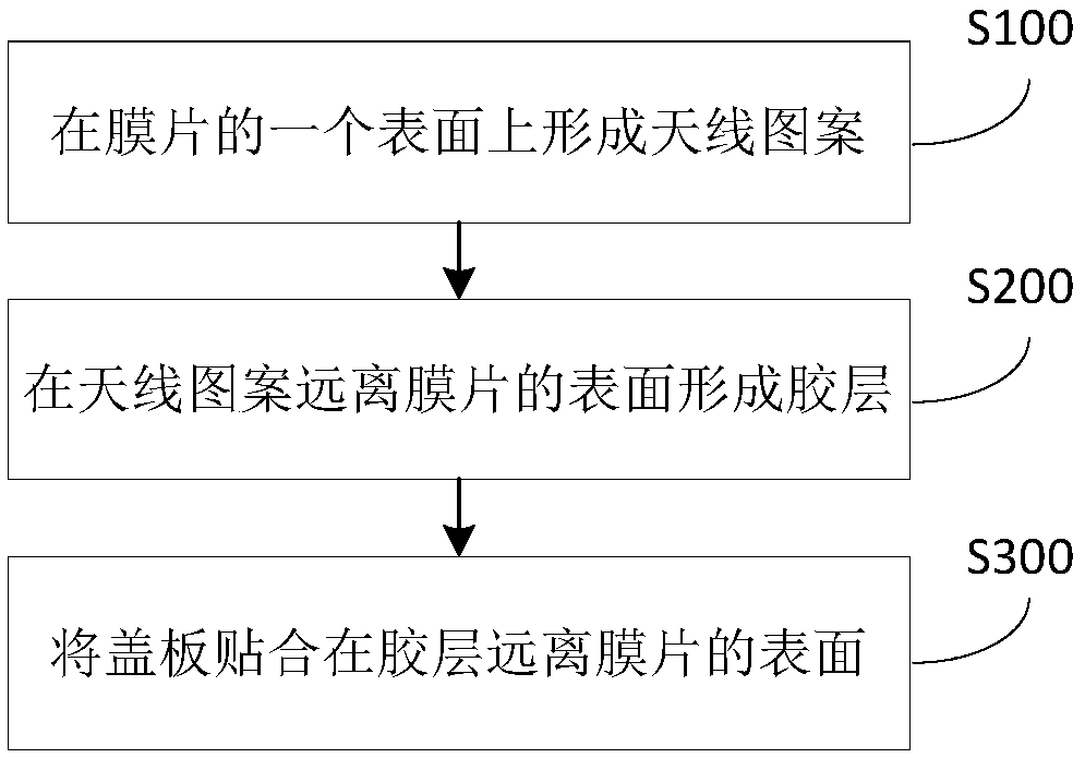
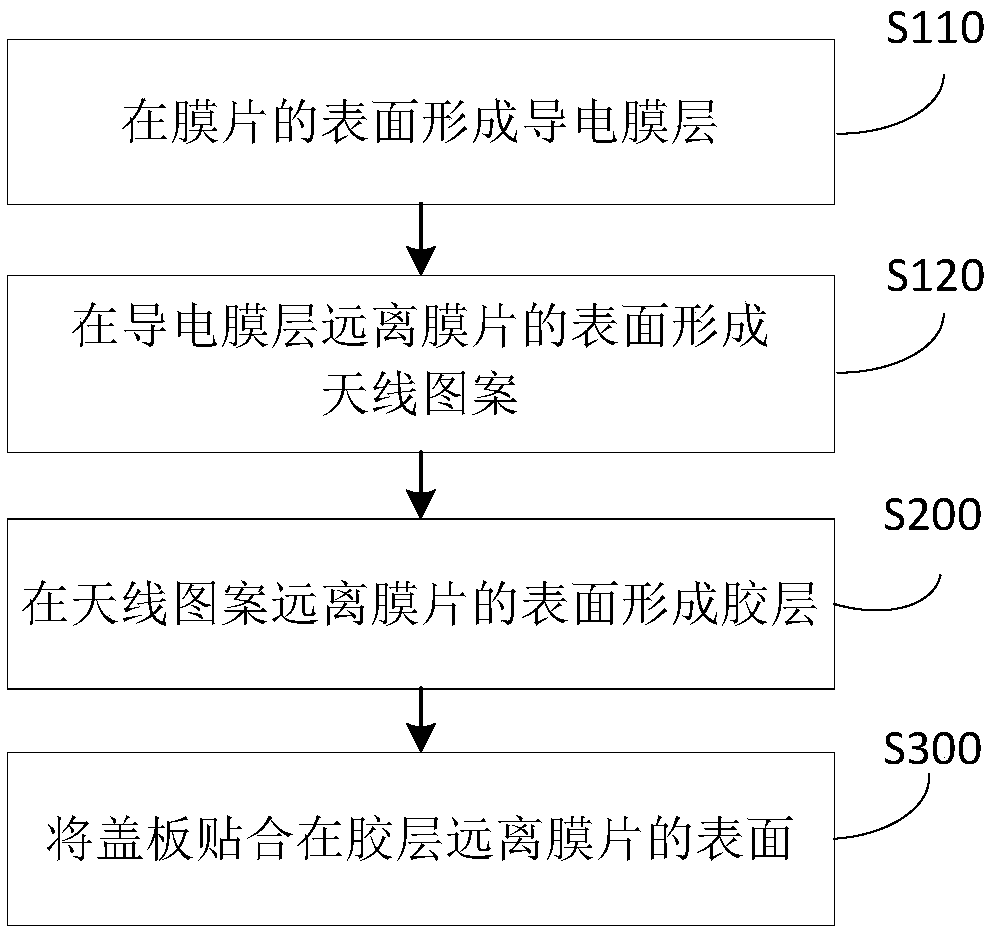
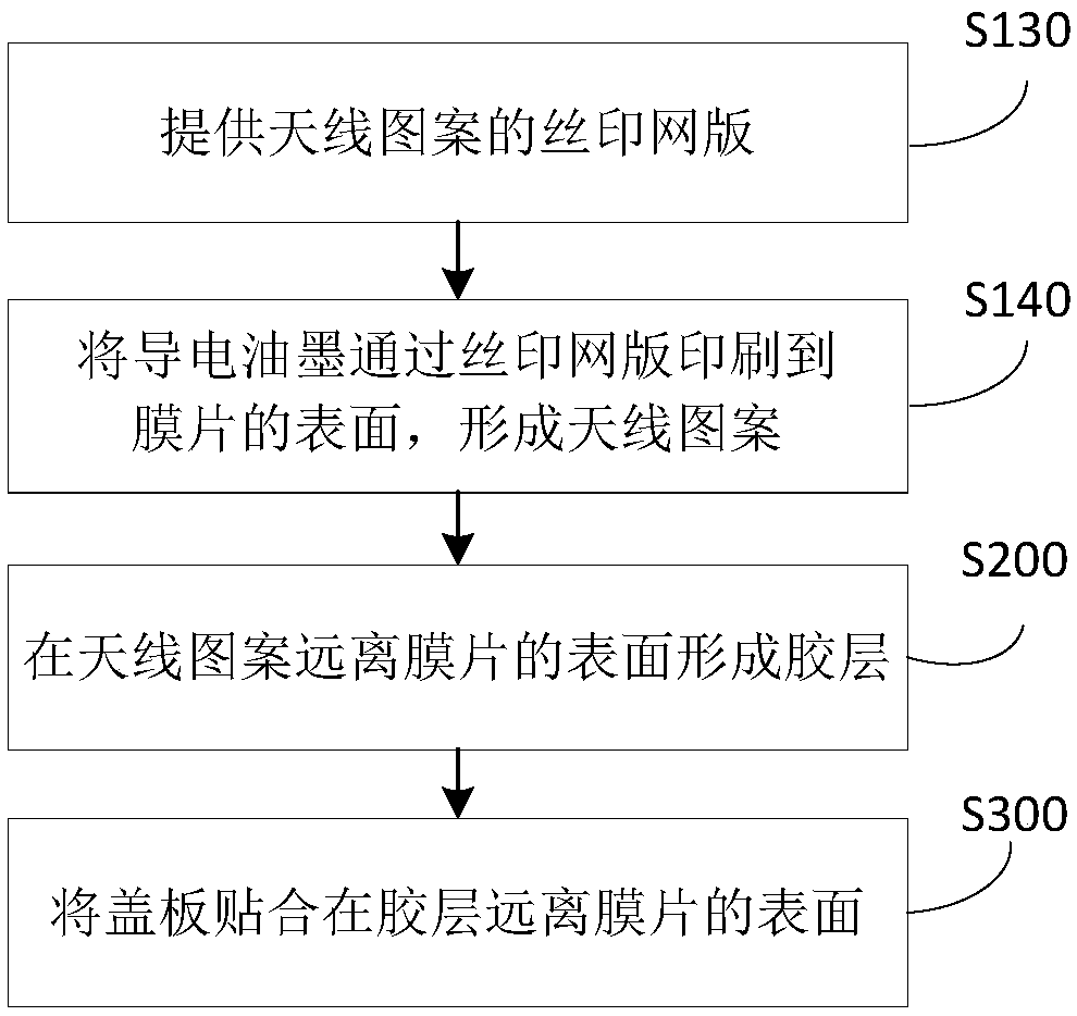
[0033] In one aspect of the embodiments of the present invention, a method for manufacturing an antenna is provided. According to an embodiment of the present invention, refer to figure 1 , the production method includes:

[0034] S100: Forming an antenna pattern on one surface of the diaphragm.

[0035] In this step, the antenna pattern 200 is first formed on one surface of the diaphragm 100 , so that the diaphragm 100 has no space restriction on the...


PUM

PropertyMeasurementUnit
Thicknessaaaaaaaaaa

Abstract

The invention provides an antenna, a manufacturing method thereof and an electronic device. The manufacturing method of the antenna comprises: forming an antenna pattern on a surface of a diaphragm; forming an adhesive layer on the surface of the antenna pattern remote from the diaphragm; attaching the cover plate to the surface of the adhesive layer away from the diaphragm. According to the invention, there is no space limitation for antenna patterning, the antenna pattern can be arranged on the diaphragm at will, and the antenna pattern can be directly bonded to the cover plate without reserving additional space on the cover plate. Moreover, the manufacturing method has the advantages of simple operation and simple process, and is suitable for manufacturing antenna patterns with complexshapes, and even can produce stereoscopic antennas on the inner edges of the curved cover plate.

Description

technical field [0001] The present invention relates to the technical field of antenna production for electronic equipment, and specifically, the present invention relates to an antenna, a production method thereof, and electronic equipment. Background technique [0002] At this stage, there are three schemes for making antennas for electronic devices such as mobile phones, tablet computers, and smart watches: the first is the flexible printed circuit board method (PFC), that is, a wire with a copper film is formed between two layers of plastic films; the second is The laser direct structuring (LDS) method is to laser engrave the shape on the plastic bracket, and then electroplate the metal; the third is the metal middle frame method, which is to use the metal middle frame of the electronic device directly as an antenna. [0003] Among them, the first two methods generally make the antenna directly on the middle frame or the back cover of the mobile phone, which will take up...

Claims


Application Information

Patent Timeline
IPC IPC(8): H01Q1/38H01Q1/24H01Q1/22B41M1/12B41M1/30
CPCB41M1/12B41M1/30H01Q1/22H01Q1/2266H01Q1/243H01Q1/38
Inventor 杨光明
Owner GUANGDONG OPPO MOBILE TELECOMM CORP LTD
Learn More