Textile drying device

A drying device and textile technology, applied in drying, drying machine, drying gas arrangement, etc., can solve the problems of inability to dry textiles and affect the drying efficiency of textiles, achieve strong practicability and applicability, and improve drying efficiency. The effect of dry efficiency

Inactive Publication Date: 2018-12-28
金伟杰
View PDF0 Cites 1 Cited by
  • Summary
  • Abstract
  • Description
  • Claims
  • Application Information

AI Technical Summary

Problems solved by technology

The existing textile drying device mainly includes a box body. A working chamber is arranged inside the box body, and a heater is arranged inside the working chamber. When in use, the textiles are put into the working chamber and the heater is turned on for drying. However, the heater of this textile drying device is fixed, and it is impossible to focus on drying the textiles locally, which affects the drying efficiency of the textiles.

Method used


Image

  • Textile drying device
  • Textile drying device
  • Textile drying device

Examples


Embodiment

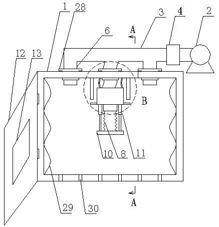
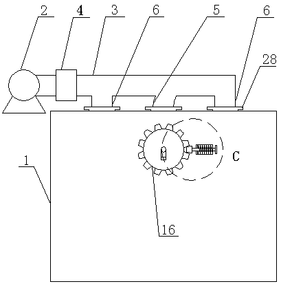
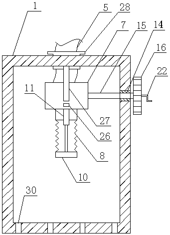
[0026] Such as Figure 1 to Figure 6 As shown, a textile drying device includes a box body 1, the upper end of the box body is provided with a fan 2, the fan is connected with a main air duct 3, and the main air duct is provided with an air heater 4, a second A pipe 5 and a second branch pipe 6, the first branch pipe and the second branch pipe are connected to the air inlet on the top of the box body, the first branch pipe passes through the air inlet port and extends to the inside of the box body until it passes through the air inlet located in the box body The support base 7, and the bottom end of the first branch pipe is connected with a bellows 8, the outer circumference of the bottom end of the bellows is fixed on the fixed plate 10 with the air outlet 9, and a telescopic cylinder is arranged between the support base and the fixed plate 11. The support seat and the box body are flexibly connected through the angle adjustment mechanism arranged on the back of the box body....


PUM


Abstract

The invention discloses a textile drying device. The textile drying device comprises a box body, a fan is arranged at the upper end of the box body, and a main air pipe is connected to the fan. The main air pipe is provided with an air heater, a first branch pipe and a second branch pipe, the first branch pipe and the second branch pipe are connected with an air inlet in the top of the box body, the first branch pipe penetrates through the air inlet and extends to the interior of the box body until penetrates through a supporting seat of the interior of the box body, and a corrugated pipe is connected at the bottom end of the first branch pipe. The periphery of the bottom end of the corrugated pipe is fixed to a fixed plate with an air outlet, a telescopic air cylinder is arranged betweenthe supporting seat and the fixed plate, the supporting seat is movably connected with the box body through an angle adjustment mechanism arranged on the back portion of the box body, a movable door is arranged on the box body, an inspection window is arranged on the movable door, and a plurality of dust fall holes are uniformly formed in a base plate of the box body in a distributed mode. The textile drying device can perform local key drying on textiles according to actual requirements, and the drying efficiency is improved.

Description

technical field [0001] The invention relates to a textile drying device, which belongs to the technical field of textile equipment. Background technique [0002] Textile is related to people's livelihood, industry and other fields. my country is a traditional textile country. In the process of textile production, drying device is one of the indispensable production equipment. The quality of drying directly affects the quality of textiles. The existing textile drying device mainly includes a box body. A working chamber is arranged inside the box body. A heater is arranged inside the working chamber. When in use, the textiles are put into the working chamber and the heater is turned on for drying. However, the heater of this textile drying device is fixedly installed, and cannot perform partial focused drying on the textiles, which affects the drying efficiency of the textiles. Contents of the invention [0003] The object of the present invention is to provide a textile dr...

Claims


Application Information

Patent Timeline
Patent Type & Authority Applications(China)
IPC IPC(8): F26B9/06F26B21/00F26B25/00
CPCF26B9/06F26B21/001F26B25/00
Inventor 金伟杰
Owner 金伟杰
Why Eureka
Try Eureka