
Swinging type hydraulic cylinder

A hydraulic cylinder and swing-type technology, which is applied in the direction of fluid pressure actuating device, etc., can solve problems such as difficult operation, increased internal leakage, and good manufacturability, so as to increase the rotation range, reduce shaft shoulder leakage, and realize gap sealing Effect

Inactive Publication Date: 2018-12-28
DONGGUAN UNIV OF TECH
View PDF2 Cites 5 Cited by
  • Summary
  • Abstract
  • Description
  • Claims
  • Application Information

AI Technical Summary

Problems solved by technology

The blade seal used is an arc-shaped lip-shaped seal plate inlaid on both sides of the blade, which is complicated to manufacture, difficult to operate, requires good manufacturability and high cost
At the same time, its shoulder leakage has not been studied for improvement
[0006] There is also a part of the previous literature, "Swing Hydraulic Cylinder Internal Structure Improvement Design", Hydraulic Pneumatics and Sealing, Issue 6, 2007, a hydrostatically supported vane swing cylinder, CN201721395360.1, a water hydraulic single vane swing cylinder , CN201610035551.0, the vane-type swing hydraulic cylinder usually adopts the rectangular vane form in the design, cooperates with the combined sealing structure of the door frame and the combined sealing of the shaft shoulder to control internal leakage; at the same time, in the design of the shape, there are Larger diameters and less compact space structures make it difficult to apply in occasions where there are more restrictions on installation space, such as robot joint drives
In addition, the sealing structure is complex, and the amount of internal leakage is also difficult to control. As the pressure difference between the high and low pressure chambers increases, the internal leakage also increases rapidly, reducing the overall efficiency and service life of the swing hydraulic cylinder
Thirdly, its maintenance difficulty, cost control and other aspects are also difficult to reach the ideal level

Method used


Image

  • Swinging type hydraulic cylinder
  • Swinging type hydraulic cylinder
  • Swinging type hydraulic cylinder

Examples


Embodiment Construction

[0030] In order to further understand the features, technical means, and specific objectives and functions achieved by the present invention, the present invention will be further described in detail below in conjunction with the accompanying drawings and specific embodiments.

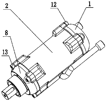
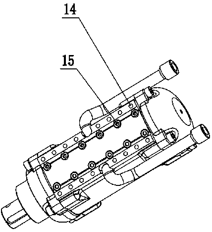
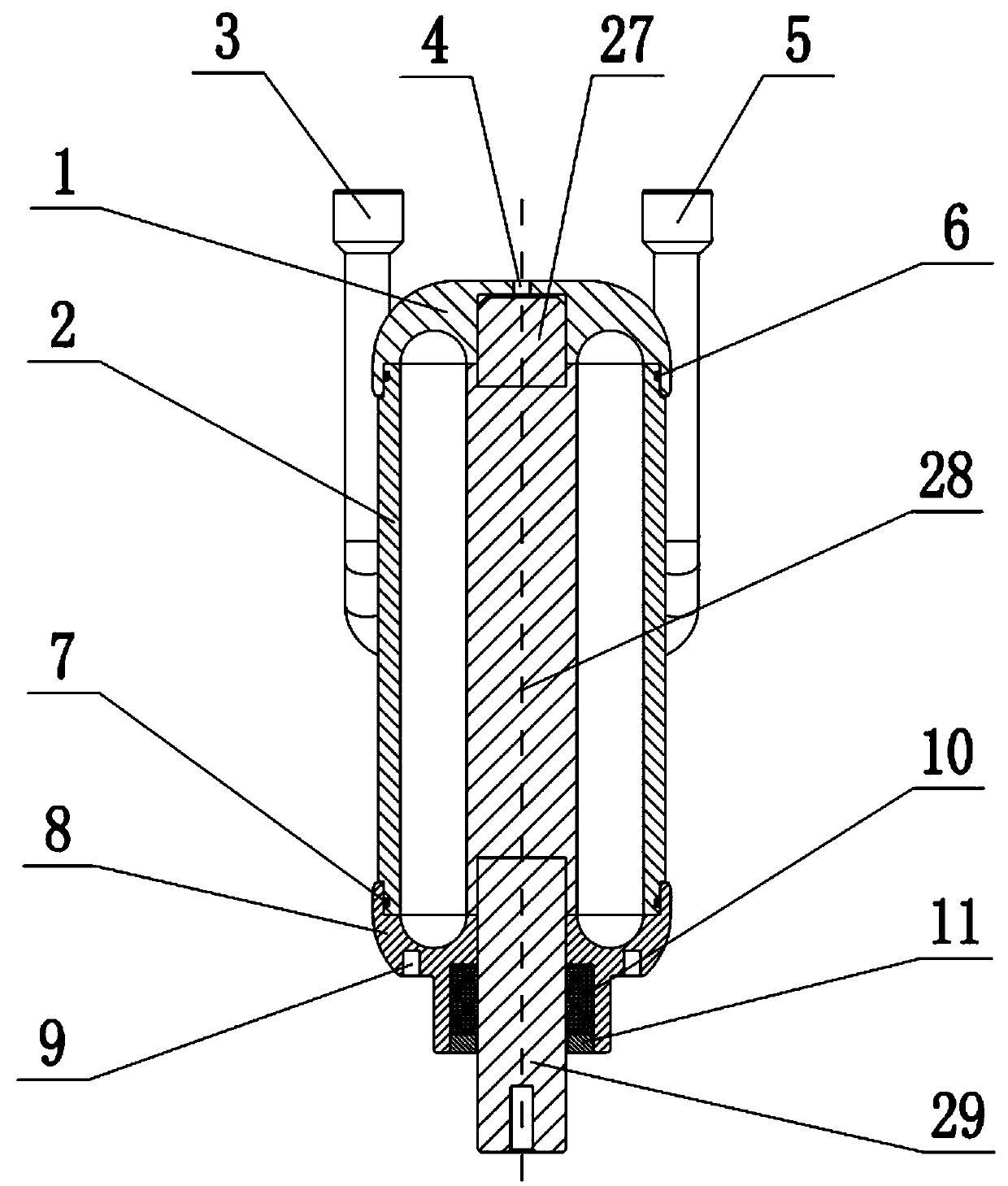
[0031] as attached figure 1 As shown in -6, the present invention discloses a swing hydraulic cylinder, which includes a cylinder body 2, a front cover 8 is provided at the front end of the cylinder body 2, a rear cover 1 is provided at the rear end, and an intermediate blade installation shaft 28 is installed in the cylinder body 2 , the side wall of the cylinder body 2 is equipped with an oil inlet pipe 3 and an oil outlet pipe 5, the rear end of the middle blade installation shaft 288 is equipped with a rear end combination shaft 27 snapped with the rear cover 1, and the front end of the middle blade installation shaft 28 is equipped with a front end The cover 8 passes through the front-end combinat...


PUM


Abstract

The invention discloses a swinging type hydraulic cylinder. The swinging type hydraulic cylinder comprises a cylinder body. A front cover is arranged at the front end of the cylinder body. A rear cover is arranged at the rear end of the cylinder body. The cylinder body is internally provided with an intermediate blade mounting shaft. An oil inlet pipe and an oil outlet pipe are arranged on the lateral wall of the cylinder body. The rear end of the intermediate blade mounting shaft is connected with a rear end combination shaft clamped in the rear cover. The front end of the intermediate blademounting shaft is connected with a front end combination shaft penetrating outside from the front cover. An oil inlet hole and an oil outlet hole communicating with the oil inlet pipe and the oil outlet pipe are formed in the inner wall of the cylinder body. A rotor blade is mounted at the intermediate blade mounting shaft. A stator blade is arranged on the inner wall of the cylinder body. The endface of the front side of the stator blade is in attaching contact with the intermediate blade mounting shaft. The front end side of the rotor blade is in attaching contact with the inner wall of thecylinder body. Two annular sealing cavities are formed by the cylinder body, the front cover, the rear cover, the rotor blade and the stator blade. The sealing performance is excellent. Rotation stability is improved. Stability and reliability of cylinder movement are improved. The machining cost is lowered.

Description

technical field [0001] The invention belongs to the application field of hydraulic drive technology, and the purpose of the invention is to design a vane swing hydraulic cylinder with compact structure, good sealing performance and smaller internal leakage compared with traditional swing hydraulic cylinders. Background technique [0002] The vane type swing hydraulic cylinder has the advantages of large output torque, compact structure and large swing angle, and has been widely used in various construction machinery equipment, transportation, robots and various special operation equipment. The vane swing cylinder mainly includes two designs: single vane and double vane. Generally, the maximum rotation of a single-blade swing cylinder is less than 300°; the maximum rotation angle of a double-blade swing cylinder is less than 120°. [0003] The sealing section of the traditional vane-type swing cylinder is usually rectangular, and the sealing of the vane is difficult, requiri...

Claims


Application Information

Patent Timeline
Patent Type & Authority Applications(China)
IPC IPC(8): F15B15/12
CPCF15B15/12
Inventor 张超张兵朱建军楚豫川
Owner DONGGUAN UNIV OF TECH
Learn More