
Composite turbomachine component and related methods of manufacture and repair

A technology for turbines and turbine blades, used in the manufacture of tools, engine components, mechanical equipment, etc., to solve problems such as cracking or other material fatigue

Inactive Publication Date: 2018-12-28
GENERAL ELECTRIC CO
View PDF8 Cites 0 Cited by
  • Summary
  • Abstract
  • Description
  • Claims
  • Application Information

AI Technical Summary

Problems solved by technology

These tensile stresses can contribute to cracking or other material fatigue and may eventually require repair and / or maintenance

Method used


Image

  • Composite turbomachine component and related methods of manufacture and repair
  • Composite turbomachine component and related methods of manufacture and repair
  • Composite turbomachine component and related methods of manufacture and repair

Examples


Embodiment Construction

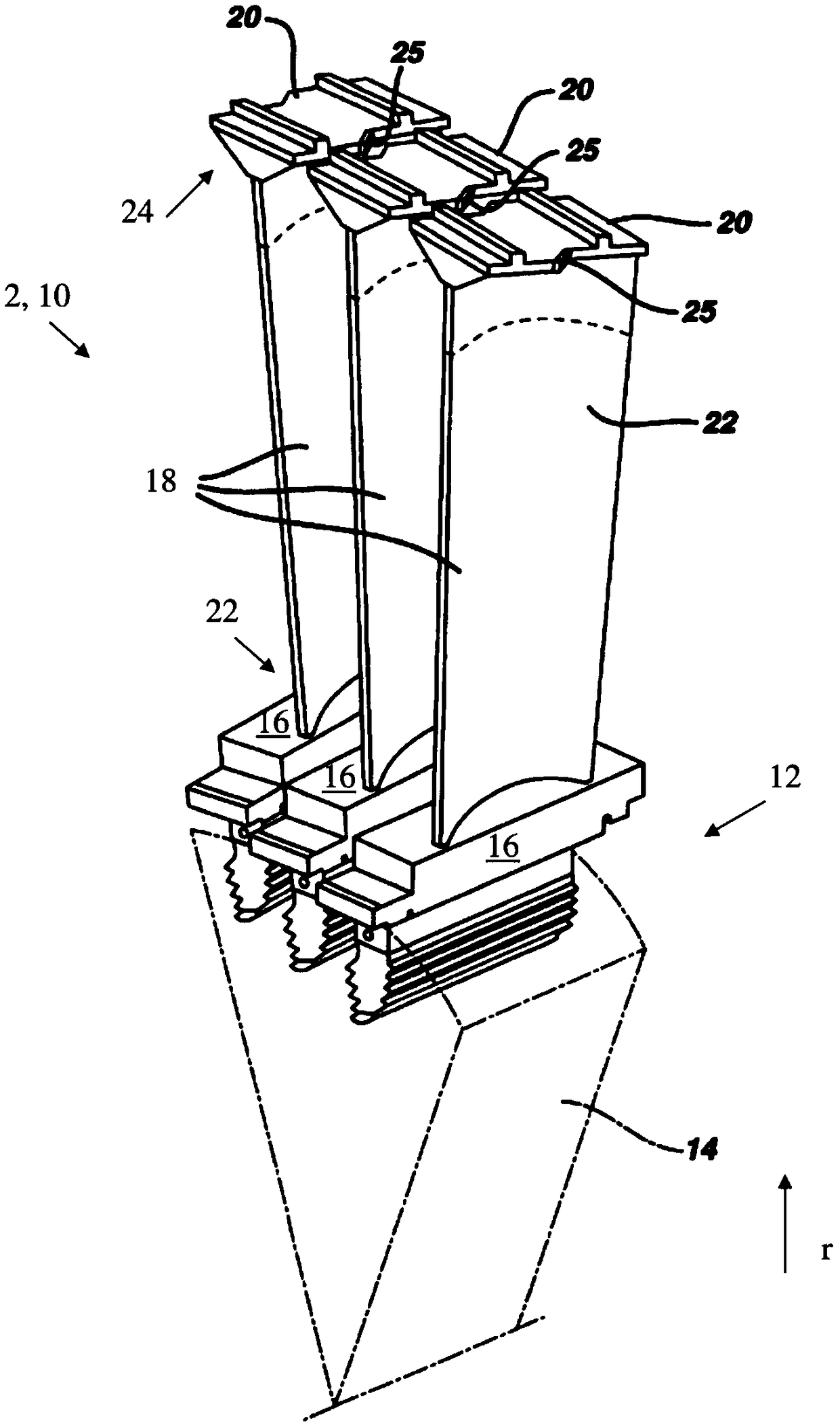
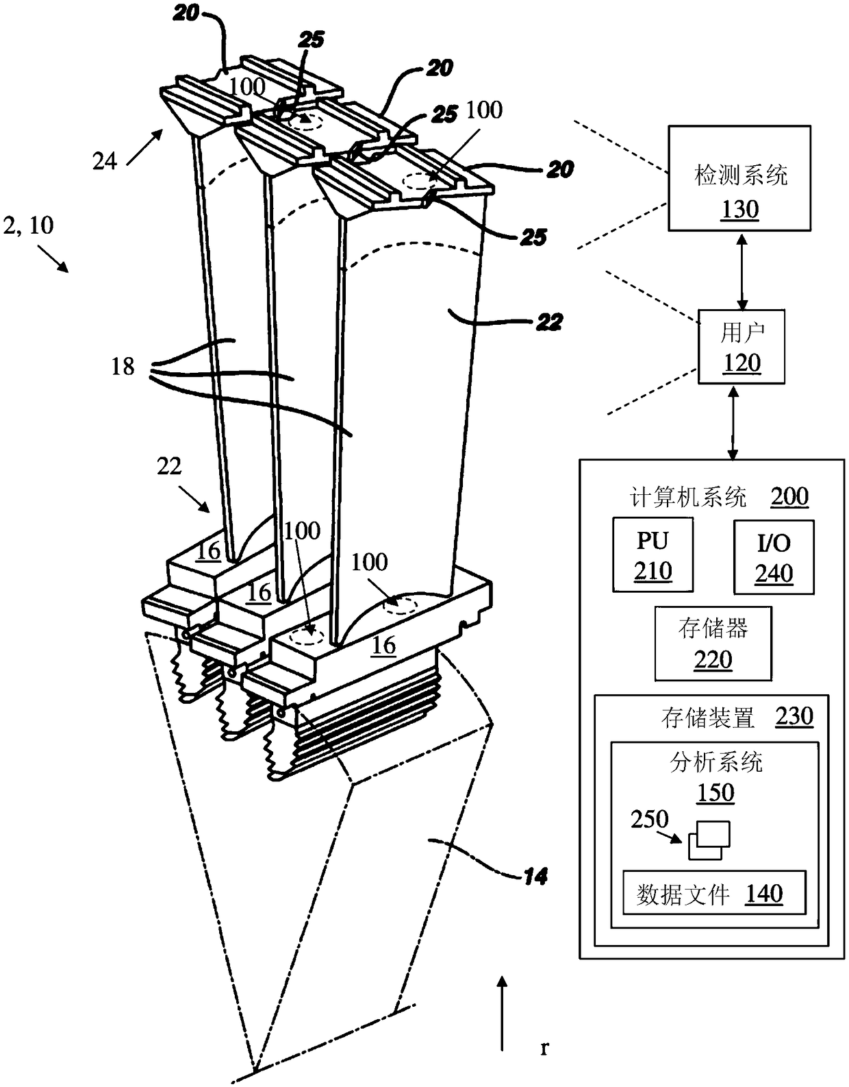
[0038] The subject matter disclosed herein relates to manufacture and / or repair. More specifically, the subject matter disclosed herein relates to composite components using materials having different coefficients of thermal expansion, and methods of forming those components.

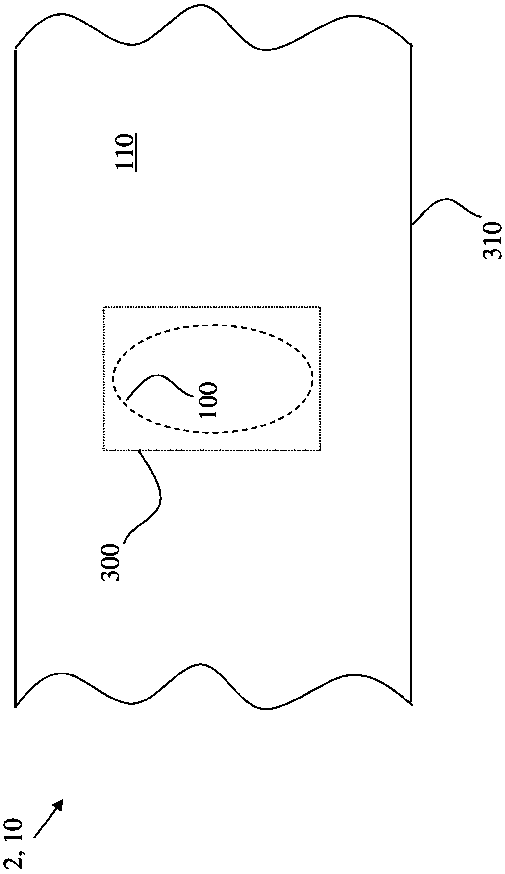
[0039]Aspects of the present disclosure include composite turbine components, and methods of forming such components, as compared to conventional approaches. In various embodiments, a composite turbine component has a body and an insert filling a slot in the body, wherein the location of the slot is determined based on an expected or actual amount of material fatigue in the portion of the body. The insert may be welded to the body at the slot, but in some cases the insert may also be brazed to the body at the slot. In various embodiments, the body of the turbine component is formed from steel or an alloy, such as at least one nickel-chromium superalloy, at least one cobalt-based superalloy, or at least...


PUM


Abstract

The invention provides various aspects including a composite turbomachine component and related methods. In some cases, a method includes: identifying a location of potential or actual structural weakness in a body of a turbomachine component, the body including a first material having a first thermal expansion coefficient; forming a slot in the location of the body, the slot extending at least partially through a wall of the turbomachine component; and bonding an insert to the body at the slot to form a composite component, the insert including a second material having a second thermal expansion coefficient differing from the first thermal expansion coefficient by up to approximately ten percent, the second material consisting of a nickel-chromium-molybdenum alloy, wherein after the bonding the insert is configured to reduce the potential or actual structural weakness in the body.

Description

technical field [0001] The subject matter disclosed herein relates to the manufacture and repair of components. More specifically, the subject matter disclosed herein relates to ways to manufacture and / or repair components to manage material stress. Background technique [0002] During operation, turbine components such as turbine blades and nozzles are subjected to high temperatures, pressure, and / or stress for extended periods of time. Under many conditions, certain portions of these components may experience differential stresses due to their geometry and position relative to the working fluid (eg, gas or vapor). For example, a blade platform or tip or a nozzle sidewall may experience different heating and cooling rates compared to an airfoil of the same blade or nozzle. This differential thermal inertia can induce tensile stress at or near the platform and / or tip (or sidewall). These tensile stresses can contribute to cracking or other material fatigue, and eventually...

Claims


Application Information

Patent Timeline
Patent Type & Authority Applications(China)
IPC IPC(8): B23K31/02F01D5/14F01D5/28
CPCB23K31/02F01D5/147F01D5/28F05D2300/171B23P6/005F01D5/005F01D5/225F05D2230/80F05D2300/175F05D2230/232F05D2230/237F05D2230/10F05D2300/131F05D2300/50211F05D2240/30F05D2240/80F05D2260/81F05D2260/83F05D2260/941F05D2300/50212F05D2300/603
Inventor W.F.西特基维奇A.M.楚克-卡曼斯基M.加卡A.盖克P.A.克林楚克M.科瓦尔茨克R.利斯基维奇M.帕库塞夫斯基S.P.瓦辛格M.沃切乔夫斯基
Owner GENERAL ELECTRIC CO
Learn More