Automobile engine oil level gauge tube and device welded with metal support thereof
A technology for automobile engines and metal brackets, applied in auxiliary devices, welding equipment, metal processing equipment, etc., can solve problems such as easily causing harm, pollute the environment and human health, and achieve the effect of preventing pollution
Inactive Publication Date: 2018-12-28
颜全聪
View PDF10 Cites 0 Cited by
- Summary
- Abstract
- Description
- Claims
- Application Information
AI Technical Summary
Problems solved by technology
The current brazing furnace produces exhaust gas in the brazing curtain room during the brazing process, and the exhaust gas is directly discharged through its exhaust. While polluting the environment, it is easy to cause harm to human health because the exhaust gas contains toxic gases and particles.
Method used
View moreImage
Smart ImageViewing Examples
Examples
Embodiment Construction
Login to View More PUM
 Abstract
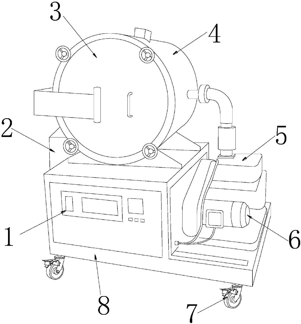
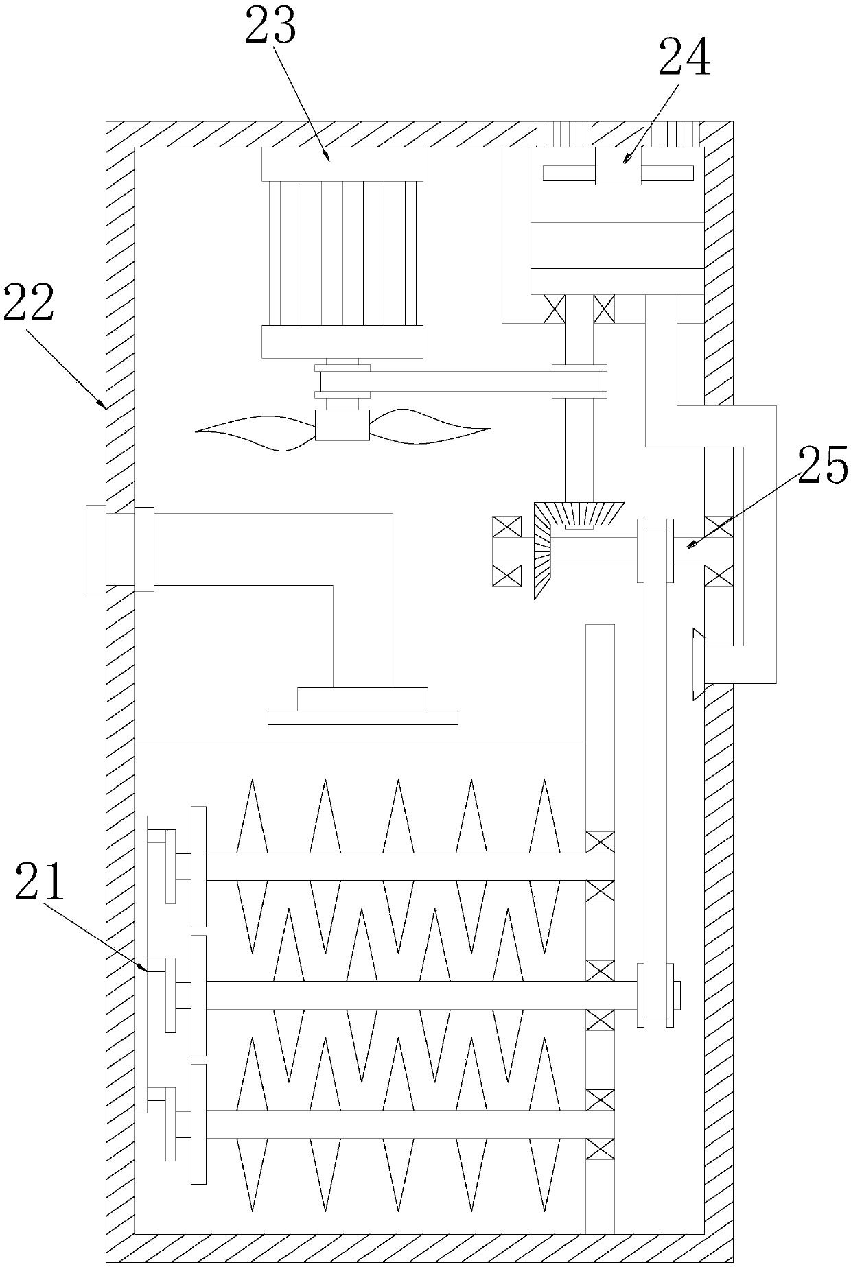
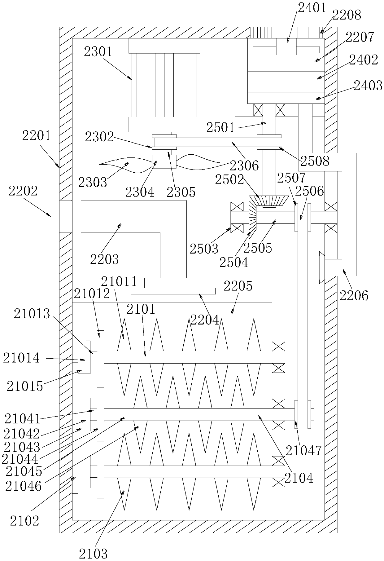
The invention discloses an automobile engine oil level gauge tube and a device welded with a metal support thereof. The device structurally comprises a control panel, a waste gas treatment device, a flange cover, a brazing furnace body, a vacuum pump, an efficient energy-saving motor, full-brake trundles and a supporting frame. Compared with the prior art, the device has the advantages that through combined arrangement of a stirring mechanism, a waste gas treatment box, a main power transmission mechanism, an outgoing gas treatment mechanism and an auxiliary power transmission mechanism, the device has a function of two-stage treatment of waste gas, two-stage treatment of the waste gas generated in a brazing machine body can be realized, first-stage treatment refers to allowing waste gas treatment liquid to be stirred with the waste gas by the stirring mechanism for sufficient reaction, and second-stage treatment refers to filtering the gas after going through first-stage treatment through a bilayer filtering layer, so that clean air can be discharged, environment pollution is prevented effectively, and harm to physical and mental health of a human body is avoided.
Description
technical field The invention relates to the technical field of auto parts welding, in particular to a device for welding an automobile engine oil dipstick conduit and its metal support. Background technique The engine is the heart of the car. There are many metal surfaces that rub against each other in the engine. These parts move fast and the environment is poor. The working temperature can reach 400°C to 600°C. Under such harsh working conditions, sufficient lubricating oil is needed to reduce the wear of engine parts and prolong the service life. The function of the oil dipstick conduit and the oil dipstick is to regularly check the liquid level of the lubricating oil in the engine to see if there is a lack of lubricating oil. The welding method of the main pipe of the existing oil dipstick and its metal support is: by adopting spot welding first to form a semi-finished product, then putting welding wire on the welding part of the semi-finished product, finally sending...
Claims
Login to View More Application Information
Patent Timeline
 Patent Type & Authority Applications(China)
IPC IPC(8): B23K1/008B23K3/08
CPCB23K1/008B23K3/08
Inventor 颜全聪
Owner 颜全聪
- R&D Engineer
- R&D Manager
- IP Professional
- Industry Leading Data Capabilities
- Powerful AI technology
- Patent DNA Extraction
Learn More Browse by: Latest US Patents, China's latest patents, Technical Efficacy Thesaurus, Application Domain, Technology Topic, Popular Technical Reports.
© 2024 PatSnap. All rights reserved.Legal|Privacy policy|Modern Slavery Act Transparency Statement|Sitemap|About US| Contact US: help@patsnap.com


