
Multifunctional pump station and control method thereof

A control method and multi-functional technology, applied in pump control, liquid variable capacity machinery, telephone communication, etc., can solve the problems of too simple electrical control mode, insufficient automation, and long construction time, so as to improve the efficiency of irrigation and fertilization , facilitate later maintenance and reduce the burden of fertilization

Inactive Publication Date: 2018-12-25
JIAXING XINMINGYUAN SPRINKLER IRRIGATION EQUIP CO LTD
View PDF13 Cites 9 Cited by
  • Summary
  • Abstract
  • Description
  • Claims
  • Application Information

AI Technical Summary

Problems solved by technology

The pump rooms of traditional pumping stations are mostly brick-concrete structures, which occupy a large area and take a long time to construct. Moreover, the electrical control methods of traditional pumping stations are too simple, the degree of automation is not high enough, and there are shortcomings such as complicated and difficult management and maintenance. To adapt to the development needs of agricultural modernization and informatization, people have carried out long-term explorations. For example, a Chinese patent discloses an integrated intelligent pump station [application number: CN201610877887.1], including a pump room, a water pump unit, and a vacuum pumping system , pipes, valves, cameras, human infrared detectors, alarms, ventilation equipment, door limit sensors, LCD screens, observation holes, card readers and control cabinets; cameras, human infrared detectors, alarms are installed on the four sides of the pump room There is also a video camera in the pump room, and a door limit sensor, LCD display, observation hole, card reader and air intake window are installed on the pump room door; the door limit sensor is used to judge whether the pump room door is It can be opened or closed; the LCD screen directly displays all the operating data of the pump station; the observation hole is convenient for the user to observe the internal conditions of the pump room without opening the door; the card reader is used to swipe the card to control the operation of the pump; , valves, water flow meters, vacuum system and control cabinet; part of the water inlet of the pipeline extends outside the pump room, and the other part is in the pump room and connected to the water inlet of the pump. The water pump and the motor are connected by shaft or belt. The water outlet is equipped with an electric butterfly valve. The electric butterfly valve is connected to a straight pipe section and then connected to the water flow meter pipe. The other end of the water flow meter is the water outlet pipe section. One part is inside the pump room and the other part is outside the pump room.
[0003] The above scheme proposes an intelligent pumping station with a high degree of automation, which can better adapt to the development needs of agricultural modernization and informatization, but the above scheme still has room for improvement. For example, when the pumping station fails, use the above The intelligent pumping station of the solution cannot perform self-inspection and remote fault diagnosis, which leads to problems such as difficulties in later maintenance; and the above-mentioned pumping station is also unable to settle the cost of starting and stopping the pumping station for users, and there is a problem of inconvenient management

Method used


Image

  • Multifunctional pump station and control method thereof
  • Multifunctional pump station and control method thereof
  • Multifunctional pump station and control method thereof

Examples


Embodiment 1

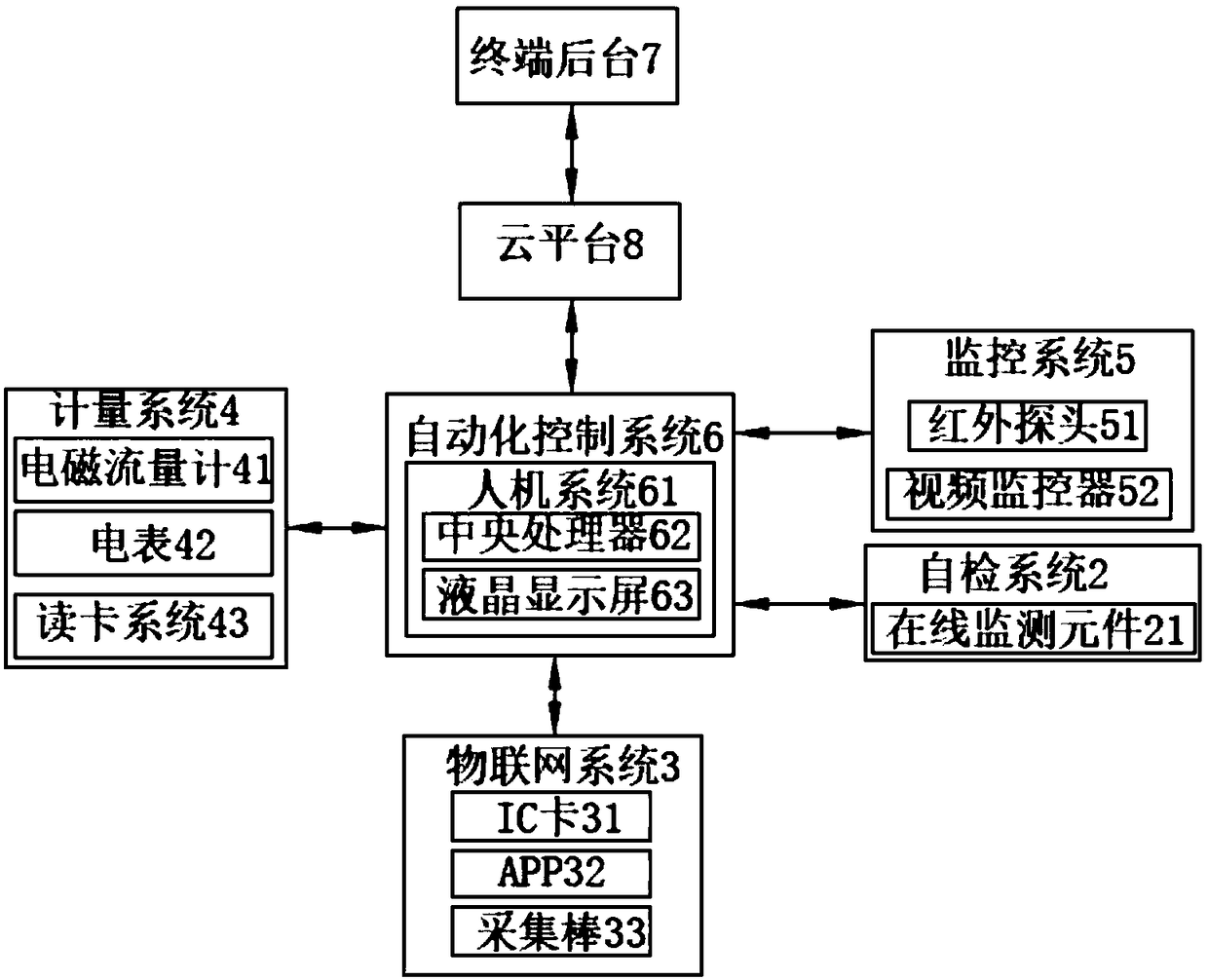
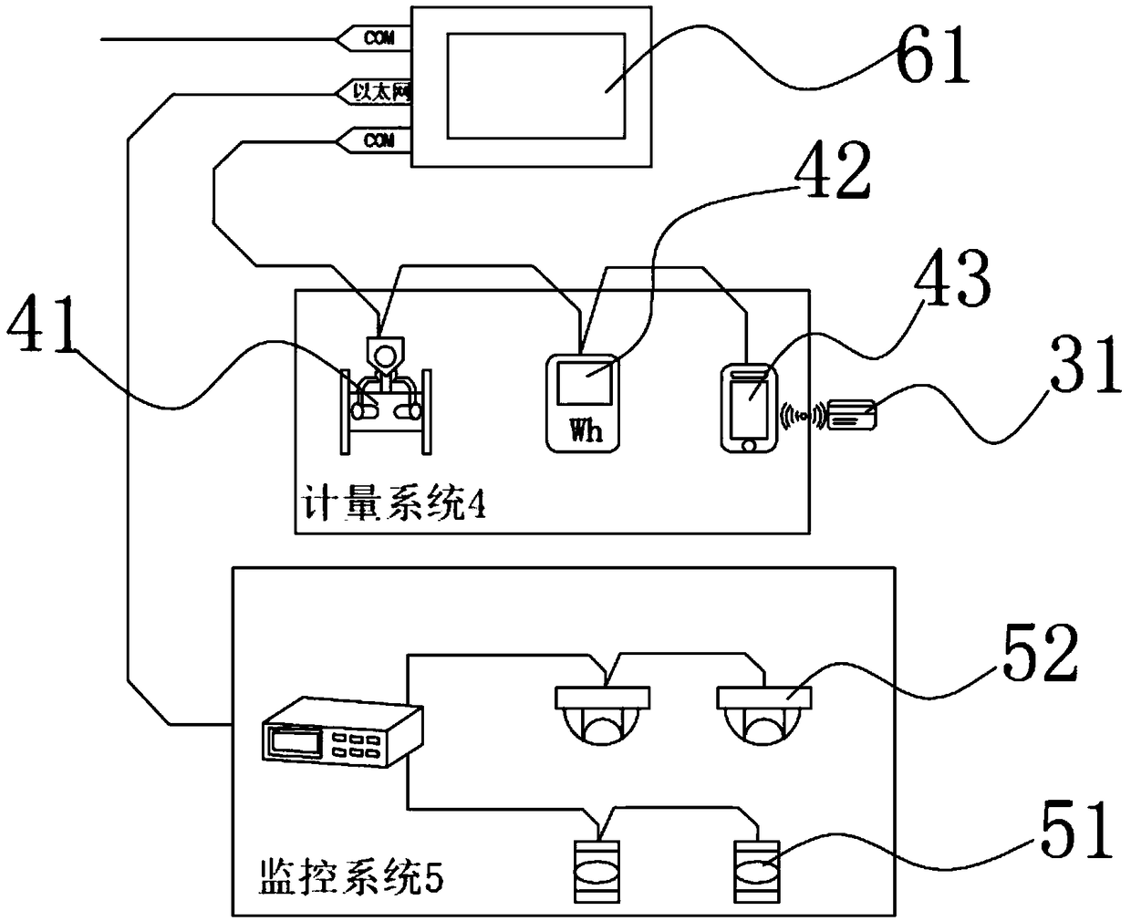
[0044] This embodiment discloses a figure 1The multi-functional pumping station shown, and the multi-functional pumping station specifically includes pump room 1, water pump unit, vacuum pumping or water injection system, pipeline system, intelligent electrical system (including circuit breaker, thermal overload protector, motor protector, frequency conversion and other equipment), Internet of Things system 3, metering system 4, monitoring system 5, automatic control system 6, self-inspection system 2 and other modules, the aforementioned multiple modules, such as water pump unit, vacuum or water injection system, pipeline system, intelligent electrical system They all use the solutions of the prior art, and this embodiment only describes the improvements in detail, and does not describe the arrangement, structure and working principle of the modules of the prior art here.

[0045] Specifically, the structure of the pump room 1 is as follows figure 2 As shown, the pump house...

Embodiment 2

[0054] This embodiment is similar to Embodiment 1, the difference is that, as Figure 5 As shown, the pumping station of this embodiment also includes a dual power supply system 700. The dual power supply system 700 includes a dual power supply conversion module 701, and a mains power system 702 and a solar battery system 703 connected to the dual power supply conversion module 701. The dual power supply conversion The other end of the module 701 is connected to each power consumption system of the pumping station to deliver the mains power or solar battery power to the pumping station, such as Figure 6 As shown, the solar battery system 703 includes a solar battery panel 704 and a photovoltaic inverter 705, the solar battery panel 704 is connected to the photovoltaic inverter 705, and the photovoltaic inverter 705 is connected to each electrical equipment of the pump room 1 and the well house 800 The submersible pump 801 etc.

Embodiment 3

[0056] This embodiment is similar to Embodiment 1 or Embodiment 2, the difference is that this embodiment also includes an automatic fertilization unit, such as Figure 7 As shown, the automatic fertilization unit includes a plurality of fertilizer bins 100 storing corresponding fertilizers, wherein the fertilizer output pipeline 101 of each fertilizer bin 100 is connected to the mixing bin 200, and the fertilizer output pipeline 101 of each fertilizer bin 100 is connected to the fertilizer bin 100. A solenoid valve 300 and a peristaltic pump 400 are provided, and the peristaltic pump 400 is connected to the automatic control system 6; wherein, the upper limit sensor 64, the middle limit sensor 65 and the lower limit sensor 66 are arranged in the mixing chamber 200 from top to bottom and the mixing bin 200 has a flow meter F corresponding to each fertilizer bin 100 respectively.

[0057] Further, the mixing output pipeline 201 of the mixing chamber 200 is connected to the wate...


PUM


Abstract

The invention discloses a multifunctional pump station and a control method thereof. The method comprises the following steps: A. equipment self-testing, feeding back abnormal information detected byan on-line monitoring element arbitrarily arranged in the pump station to a central processor, and sending the abnormal information to a background of a terminal; B. remote fault diagnosis, periodically or remotely starting the fault diagnosis program through the background of the terminal for on-line maintenance; C. remote monitoring, wherein a terminal background sends a rotation adjusting command to a central processing unit to adjust a rotating ball machine probe to obtain comprehensive field video information; D. process automation control, receiving the card swiping information or APP control information of the user on the card reader, turning on or off the corresponding water pump according to the card swiping information or APP control information, and calculating the cost of the IC card or APP account of the user. The invention has the advantages of meeting the needs of agricultural modernization, facilitating the management of the pumping station and the irrigation control, realizing the fertilization while irrigating, and improving the irrigation and the fertilization efficiency.

Description

technical field [0001] The invention belongs to the technical field of water conservancy irrigation, and in particular relates to a multifunctional pumping station and a control method thereof. Background technique [0002] As an important part of farmland water conservancy construction, rural irrigation pump stations have the characteristics of large quantities and wide areas. The pump rooms of traditional pumping stations are mostly brick-concrete structures, which occupy a large area and take a long time to construct. Moreover, the electrical control methods of traditional pumping stations are too simple, the degree of automation is not high enough, and there are shortcomings such as complicated and difficult management and maintenance. To adapt to the development needs of agricultural modernization and informatization, people have carried out long-term explorations. For example, a Chinese patent discloses an integrated intelligent pump station [application number: CN2016...

Claims


Application Information

Patent Timeline
Patent Type & Authority Applications(China)
IPC IPC(8): H04L29/08H04N7/18H04M1/725F04B49/06
CPCF04B49/06H04L67/025H04L67/10H04N7/18H04M1/72415
Inventor 金国强
Owner JIAXING XINMINGYUAN SPRINKLER IRRIGATION EQUIP CO LTD
Learn More