
An automatic control device for power line power supply

An automatic control device and power line technology, which is applied in the direction of panel/switch station circuit device, substation/distribution device casing, substation/switchgear cooling/ventilation, etc., which can solve the problem of poor heat dissipation performance and inconvenient operation of the control device. and other problems, to achieve the effect of preventing the spread of fire, convenient start and stop control, and easy heat dissipation

Active Publication Date: 2020-10-02
STATE GRID CORP OF CHINA +1
View PDF6 Cites 0 Cited by
  • Summary
  • Abstract
  • Description
  • Claims
  • Application Information

AI Technical Summary

Problems solved by technology

[0003] The purpose of the present invention is to provide an automatic control device for power line power supply to solve the problem of poor heat dissipation performance of the existing control device proposed in the background technology above, and the need to manually close and open electrical components such as air switches or leakage protectors, and operate Inconvenient question

Method used


Image

  • An automatic control device for power line power supply
  • An automatic control device for power line power supply
  • An automatic control device for power line power supply

Examples


Embodiment Construction

[0019] The following will clearly and completely describe the technical solutions in the embodiments of the present invention with reference to the accompanying drawings in the embodiments of the present invention. Obviously, the described embodiments are only some, not all, embodiments of the present invention. Based on the embodiments of the present invention, all other embodiments obtained by persons of ordinary skill in the art without creative efforts fall within the protection scope of the present invention.

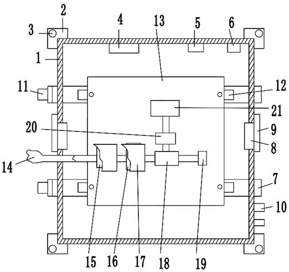
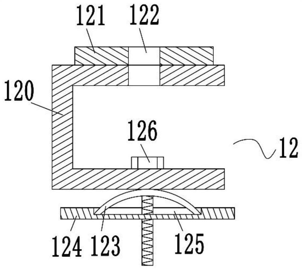
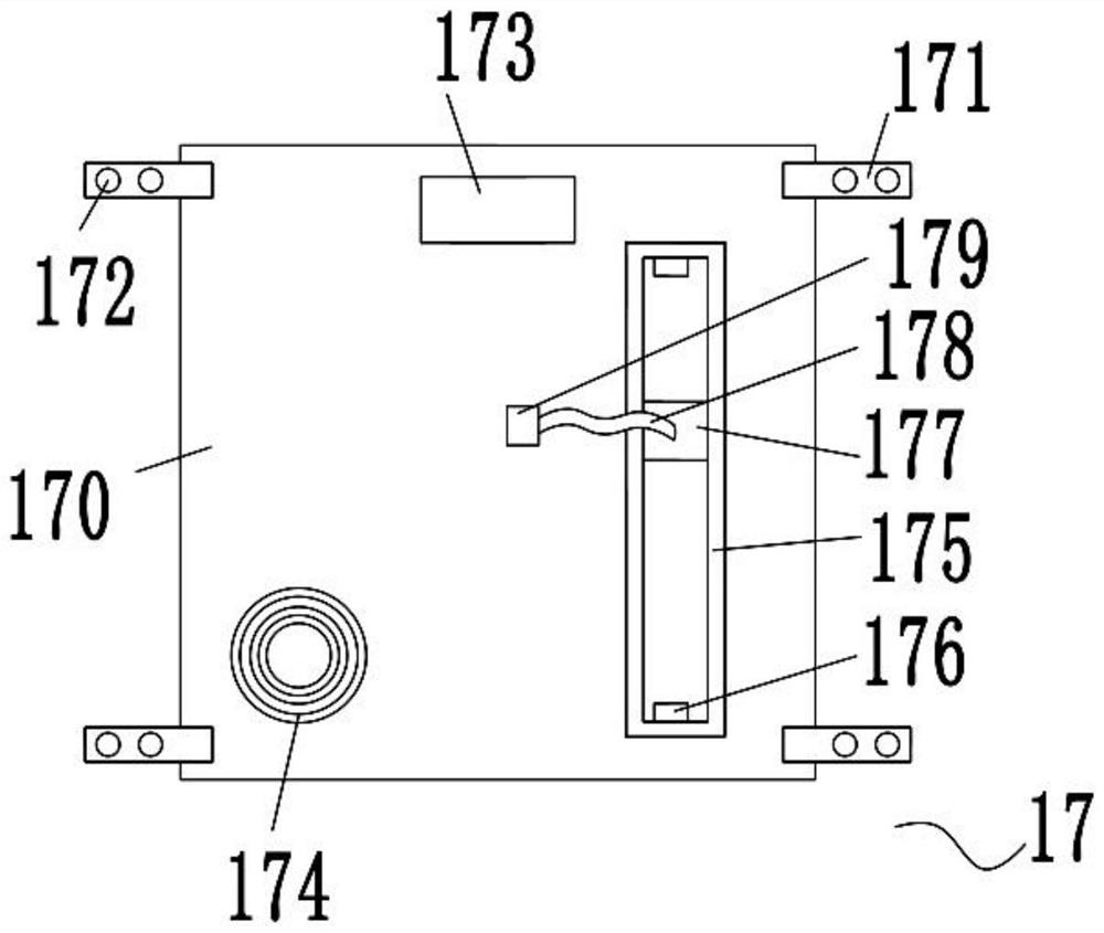
[0020] see Figure 1-3 , the present invention provides a technical solution: a power line power supply automatic control device, including a box body 1, the four corners of the rear surface of the box body 1 are provided with a mounting plate 2, and the surface of the mounting plate 2 is provided with a first mounting hole 3, A controller 4, a temperature sensor 5 and a storage battery 6 are fixed on the top of the inner cavity of the box body 1, copper pipes 7 ar...


PUM


Abstract

The invention discloses an automatic control device for power line power supply in the technical field of electric power equipment, include a box, the four corners of the rear surface of the box bodyare provided with mounting plates, the surface of the mounting plate is provided with a first mounting hole, and a controller, a temperature sensor and a battery are fixed on the top of the inner cavity of the box body, copper pipes are horizontally penetrated between the upper and lower parts of the side walls of the box body, the left and right sides of the side wall of the box body are providedwith an electric gate valve and a fire protection valve opposite to each other, two sets of wireless remote control switches are arranged at the lower part of the right side of the box body, the leftend lumen of the copper tube is provided with a heat dissipation fan through a bracket, The fine wire rope pulls the switch handle of the air switch or the current leakage protector by using a manualfixture to close the switch handle, and the electric push rod extends and presses the detection button to realize the start-stop and detection. The device can carry out real-time monitoring and remote operation, thereby facilitating heat dissipation, reducing dust entry, and facilitating start-stop control.

Description

technical field [0001] The invention relates to the technical field of electric power equipment, in particular to an automatic power supply control device for power lines. Background technique [0002] Rural power supply often has an unstable load state, often due to unstable load, resulting in overloaded power supply situation, which will cause large-scale power outages, and even burn the wires, resulting in fire hazards. In order to maintain the power supply stability of power lines, usually It is necessary to use an automatic control device to control and maintain the power line. The existing automatic control device for power line power supply is not accurate enough, and its heat dissipation performance is not good, and its safety performance is low. At the same time, it needs to be manually closed and opened, such as air switch or leakage protection. Electrical components such as appliances are inconvenient to operate. Based on this, the present invention designs an aut...

Claims


Application Information

Patent Timeline
Patent Type & Authority Patents(China)
IPC IPC(8): H02B1/48H02B1/54H02B1/56H02B1/28H02B1/24H01H3/02H01H71/10
CPCH01H3/02H01H71/10H02B1/24H02B1/28H02B1/48H02B1/54H02B1/565
Inventor 陈昌岭金轶卢峭峰王洪涛魏浩徐立盛林谭艳张力耀
Owner STATE GRID CORP OF CHINA
Learn More