Supermarket cashier device
A technology for supermarkets and cashiers, applied in the field of filters, can solve the problems of prolonged checkout time, waste of code scanning time, commodity buffer protection, etc., and achieve the effects of convenient and fast use, simple structure, and convenient operation.
- Summary
- Abstract
- Description
- Claims
- Application Information
AI Technical Summary
Problems solved by technology
Method used
Image
Examples
Embodiment 1
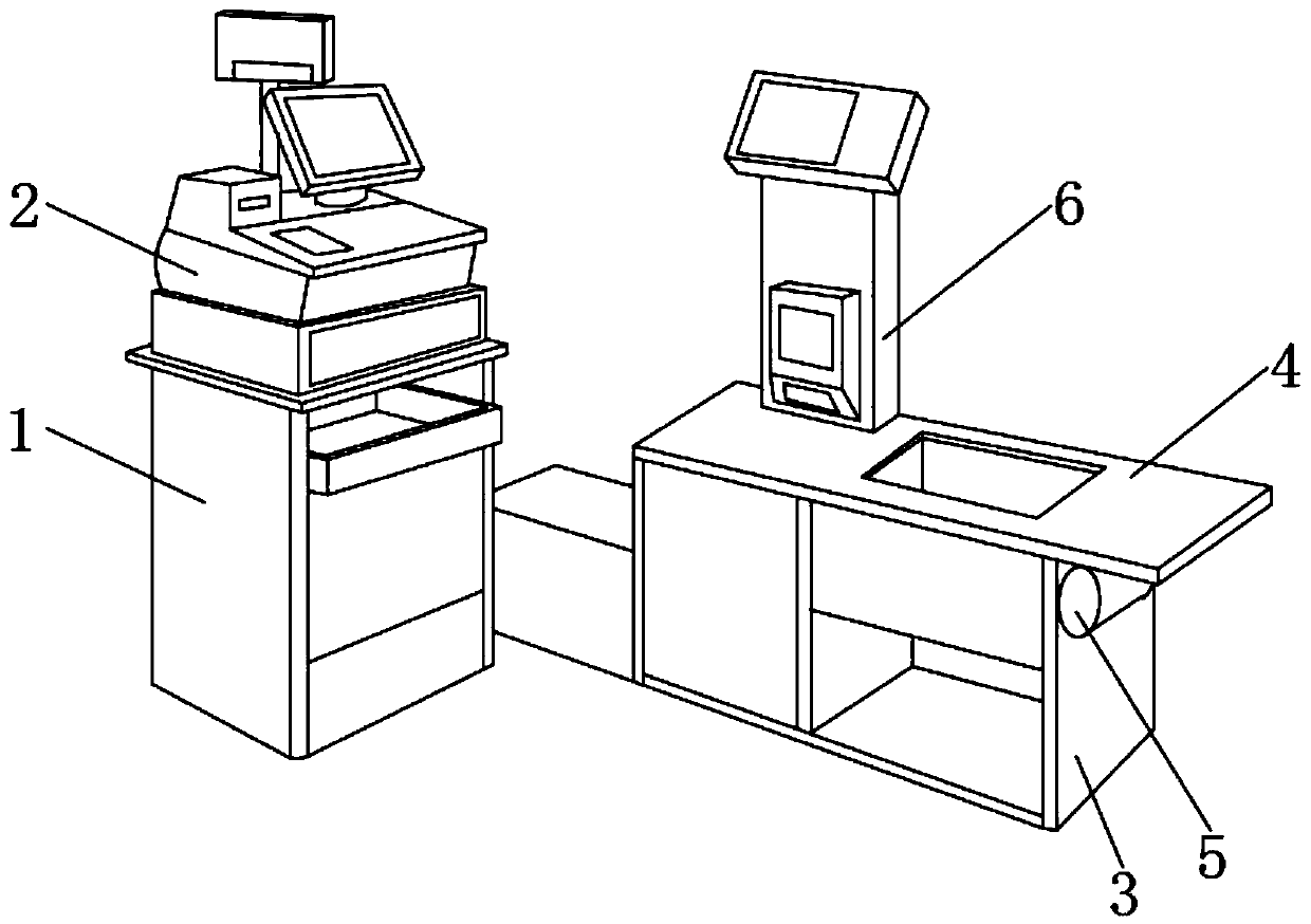
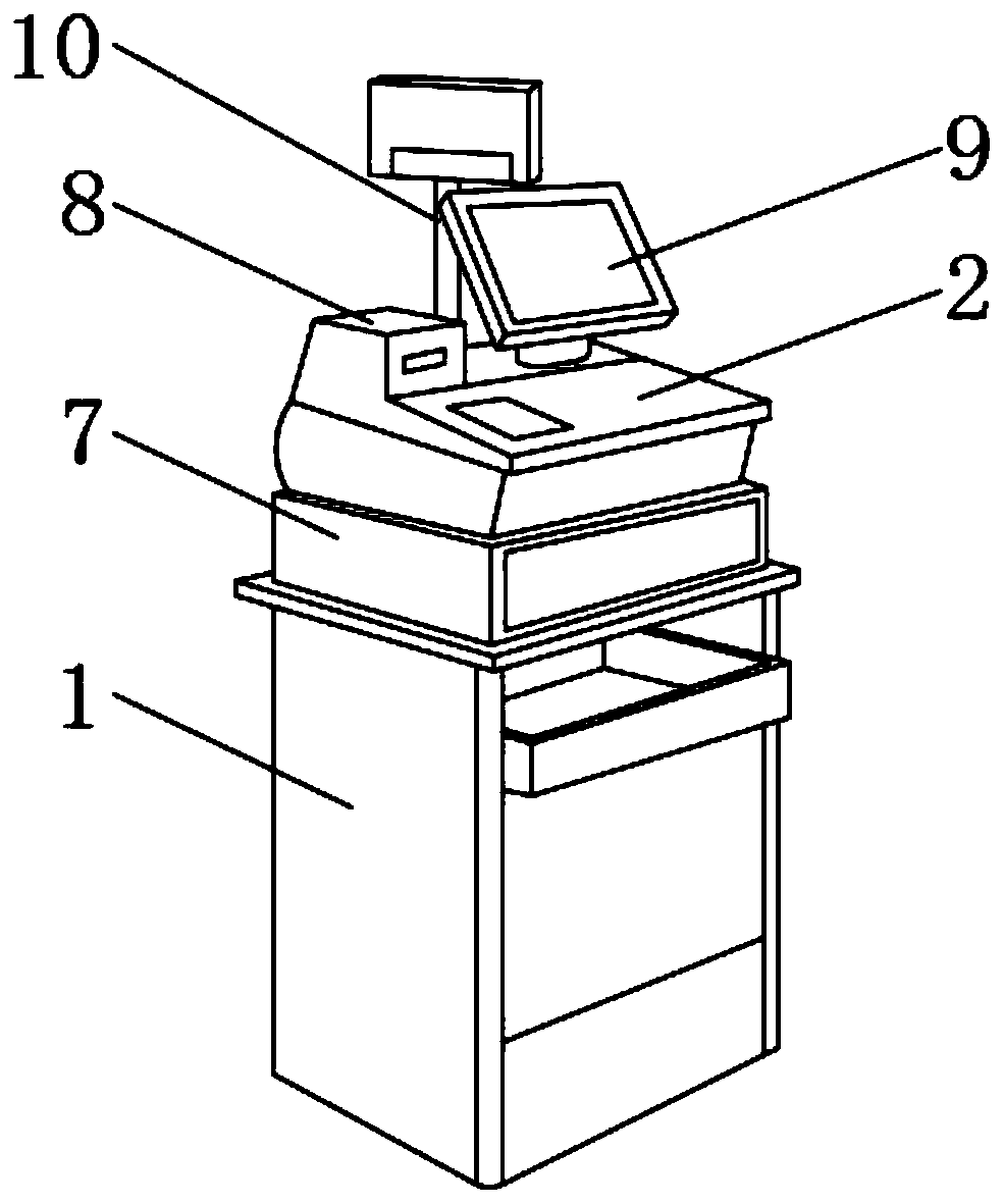
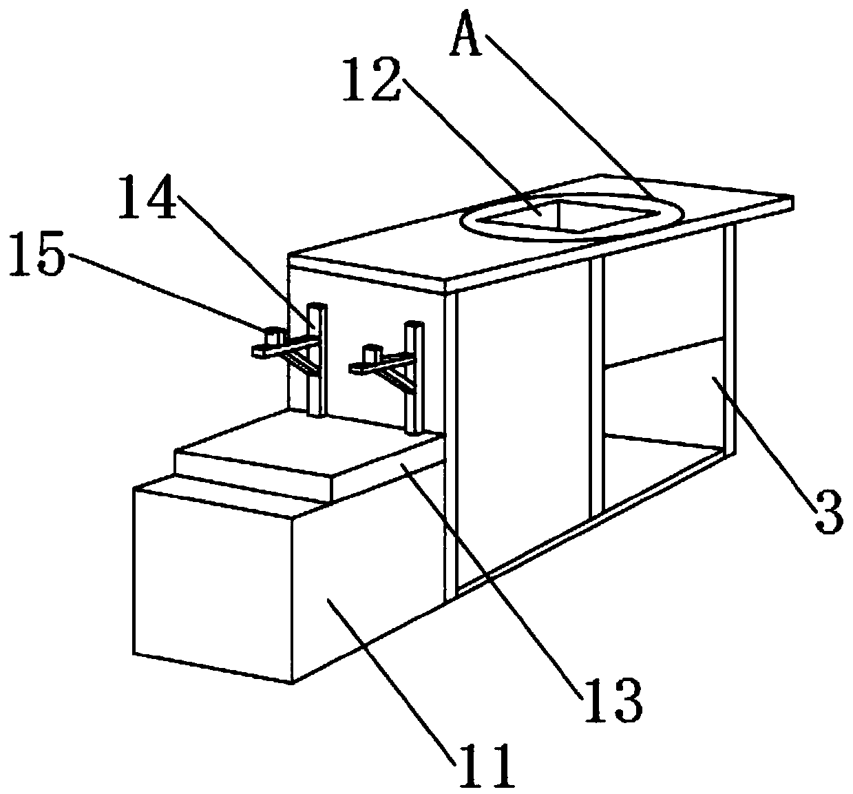
[0024] Such as Figure 1-7 As shown, a supermarket cashier device includes a cash register base 1, a cash register computer 2, a workbench base 3 and a work surface 4, the cash register computer 2 is located at the upper end of the cash register base 1, and the work surface 4 is fixedly installed on the base of the workbench 3. On the upper end, one side of the workbench base 3 is fixedly equipped with a motor 5, and the motor 5 is located at the lower end of one side of the workbench 4, and the upper end of the workbench 4 is fixedly installed with a support rod 6, and the lower end of the cash register computer 2 is fixedly installed with a cash register. Box 7, the upper end of cash register computer 2 is fixedly installed with barcode printer 8, display 9 and support 10, and barcode printer 8 is positioned at the side of display 9, and support 10 is positioned at the rear end of display 9, and the other side bottom of workbench base 3 A bagging area 11 is fixedly installed...
Embodiment 2
[0026] Such as Figure 1-7 As shown, a buffer pad 13 is fixedly installed on the upper end of the bagging area 11, and two sets of bag holders 14 are fixedly installed on the upper end of the other side of the workbench base 3, and hooks 15 are fixedly installed on the upper ends of the two sets of bag holders 14. , and the two sets of bag holders 14 are located above the buffer pad 13, the upper end of the support rod 6 is fixedly equipped with a code scanning display 16, and one side of the support rod 6 is fixedly installed with a No. 1 code scanner 17 and a No. 2 code scanner 18, And the first code scanner 17 is located at the upper end of the second code scanner 18, the upper end of the bracket 10 is fixedly equipped with a rotating shaft 19, and the upper end of the rotating shaft 19 is movably installed with a price display electronic board 20, and the upper edge position of the storage frame 12 is A chute 21 is provided, and the inside of the chute 21 is penetrated wit...
Embodiment 3
[0028] Such as Figure 1-7 As shown, a buffer pad 13 is fixedly installed on the upper end of the bagging area 11, and two sets of bag holders 14 are fixedly installed on the upper end of the other side of the workbench base 3, and hooks 15 are fixedly installed on the upper ends of the two sets of bag holders 14. , and the two sets of bag holders 14 are located above the buffer pad 13, the upper end of the support rod 6 is fixedly equipped with a code scanning display 16, and one side of the support rod 6 is fixedly installed with a No. 1 code scanner 17 and a No. 2 code scanner 18, And the first code scanner 17 is located at the upper end of the second code scanner 18, the upper end of the bracket 10 is fixedly equipped with a rotating shaft 19, and the upper end of the rotating shaft 19 is movably installed with a price display electronic board 20, and the upper edge position of the storage frame 12 is A chute 21 is provided, and the inside of the chute 21 is penetrated wit...
PUM
 Abstract
Description
Claims
Application Information
 - R&D
- Intellectual Property
- Life Sciences
- Materials
- Tech Scout
- Unparalleled Data Quality
- Higher Quality Content
- 60% Fewer Hallucinations
Browse by: Latest US Patents, China's latest patents, Technical Efficacy Thesaurus, Application Domain, Technology Topic, Popular Technical Reports.
© 2025 PatSnap. All rights reserved.Legal|Privacy policy|Modern Slavery Act Transparency Statement|Sitemap|About US| Contact US: help@patsnap.com


