
Optical fiber temperature sensor demodulation system

A fiber optic temperature and demodulation system technology, applied in thermometers, thermometers with physical/chemical changes, instruments, etc., can solve the problems that the performance of the sensor demodulation system is greatly affected, the fiber optic temperature sensor has poor adaptability, and is easily affected by temperature. , to achieve the effects of adjustable measurement sensitivity, high precision and simple production

Inactive Publication Date: 2018-12-25
张群
View PDF6 Cites 6 Cited by
  • Summary
  • Abstract
  • Description
  • Claims
  • Application Information

AI Technical Summary

Problems solved by technology

Because the optical fiber temperature sensor uses a temperature-sensitive material that matches the refractive index of the optical fiber to coat the surface of the optical fiber, the light can enter the other optical fiber from the reflection surface of one optical fiber. Influence, so that the refractive index changes, so that the output optical power is a function of temperature, so it can be used as a means to measure the change of temperature, but the common problem of optical fiber temperature sensor is poor adaptability to external environmental factors, jitter of optical signal, etc. The change of factors has a great influence on the performance of the sensor demodulation system

Method used


Image

  • Optical fiber temperature sensor demodulation system
  • Optical fiber temperature sensor demodulation system
  • Optical fiber temperature sensor demodulation system

Examples


Embodiment Construction

[0053] The present invention will be further explained below in conjunction with the accompanying drawings and specific embodiments. It should be understood that the following specific embodiments are only used to illustrate the present invention and are not intended to limit the scope of the present invention.

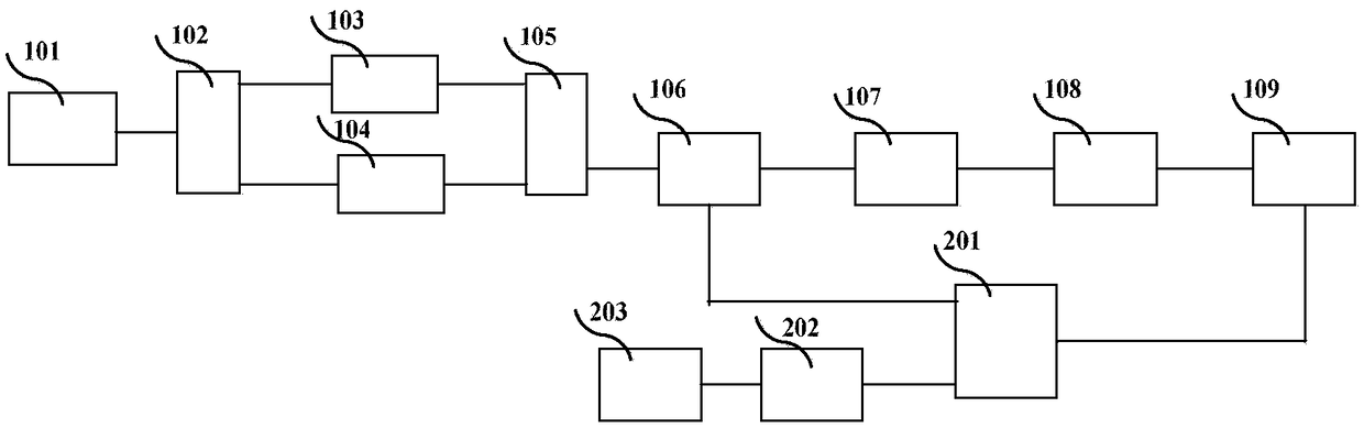
[0054] A new demodulation method for an optical fiber temperature sensor is based on the combination of an optical fiber Michelson interferometer and a photoelectric oscillator. This method changes the optical path difference of the interferometer through the change of temperature, thereby changing the center frequency of the microwave signal output by the photoelectric oscillator to realize the demodulation of optical fiber temperature sensing. The temperature measurement sensitivity can be better than 0.3°C, and it can measure Sensitivity is adjusted in real time.

[0055] Such asfigure 1 As shown, said a kind of optical fiber temperature sensor demodulation system,...


PUM


Abstract

The invention relates to an optical fiber temperature sensor demodulation system. The optical fiber temperature sensor demodulation system can solve the problems that the environmental adaptability ofan existing optical fiber temperature sensor system is poor, and factor changes such as the jitter of optical signals have great influence on the performance of the existing optical fiber temperaturesensor system. A hardware platform of the demodulation system includes a wide spectrum optical source, an optical fiber coupler, an electric adjustable optical fiber delay line, an optical fiber temperature sensing probe, an electro-optic modulator, a dispersion compensation fiber, a high-speed photodetector, a low-noise amplifier, a microwave power divider, a spectrum analyzer and a signal processing and display module. The optical fiber temperature sensor demodulation system is combined with an optical fiber Michelson interferometer and an optoelectronic oscillator to change the optical path difference of the interferometer through the change of temperature, thereby changing the center frequency of a microwave signal output by the optoelectronic oscillator and realizing the demodulationof an optical fiber temperature sensor. The temperature probe is simple in manufacturing, and temperature measurement can be achieved with ordinary single-mode optical fibers. The optical fiber temperature sensor demodulation system has the advantages of adjustable measurement sensitivity, high precision and simple measurement method.

Description

technical field [0001] The present invention is mainly used in the field of temperature measurement, and in particular relates to a fiber optic temperature sensor demodulation system. Background technique [0002] In engineering applications and scientific research, temperature is a very important reference quantity and occupies a pivotal position. Traditional temperature sensors are mainly thermocouples, semiconductors and platinum alloys. Their measurement principles are simple and cost-effective, so in practice widely used in applications. Compared with the traditional temperature sensor, the optical fiber temperature sensor uses the spectrum absorbed by some substances to change with the change of temperature, and then analyzes the spectrum transmitted by the optical fiber to measure the temperature change in real time. It has higher measurement accuracy and real-time sensitivity. adjustable. [0003] At present, fiber optic temperature sensors mainly include fiber gra...

Claims


Application Information

Patent Timeline
IPC IPC(8): G01K11/32
CPCG01K11/32
Inventor 张群
Owner 张群
Learn More