


Quick Research
Generate reliable direction feasibility study reports for your R&D in just a few steps.

Technical Q&A
Discover and master advanced knowledge NOW. Basics, ideas, possibilities, all at once.

Find Solutions
As an expert in R&D theories, this can generate solutions to your technical problems instantly.

Evaluate Feasibility
Analyze your overall solution with one click, know your potential R&D risks in advance.

Monitor Landscape
Get weekly tech updates, stay abreast of the latest tech innovations and key insights.
Fluorescent probe, fluorescence detection method, and method for using fluorescent probe
A fluorescent probe and fluorescence detection technology, applied in the field of fluorescent probes, can solve problems such as difficult to confirm fluorescently labeled cells, unable to detect fluorescence, etc.
- Summary
- Abstract
- Description
- Claims
- Application Information
AI Technical Summary
Problems solved by technology
Method used
Image

Examples
Embodiment 1
[0116] (production of fluorescent probes)
[0117]
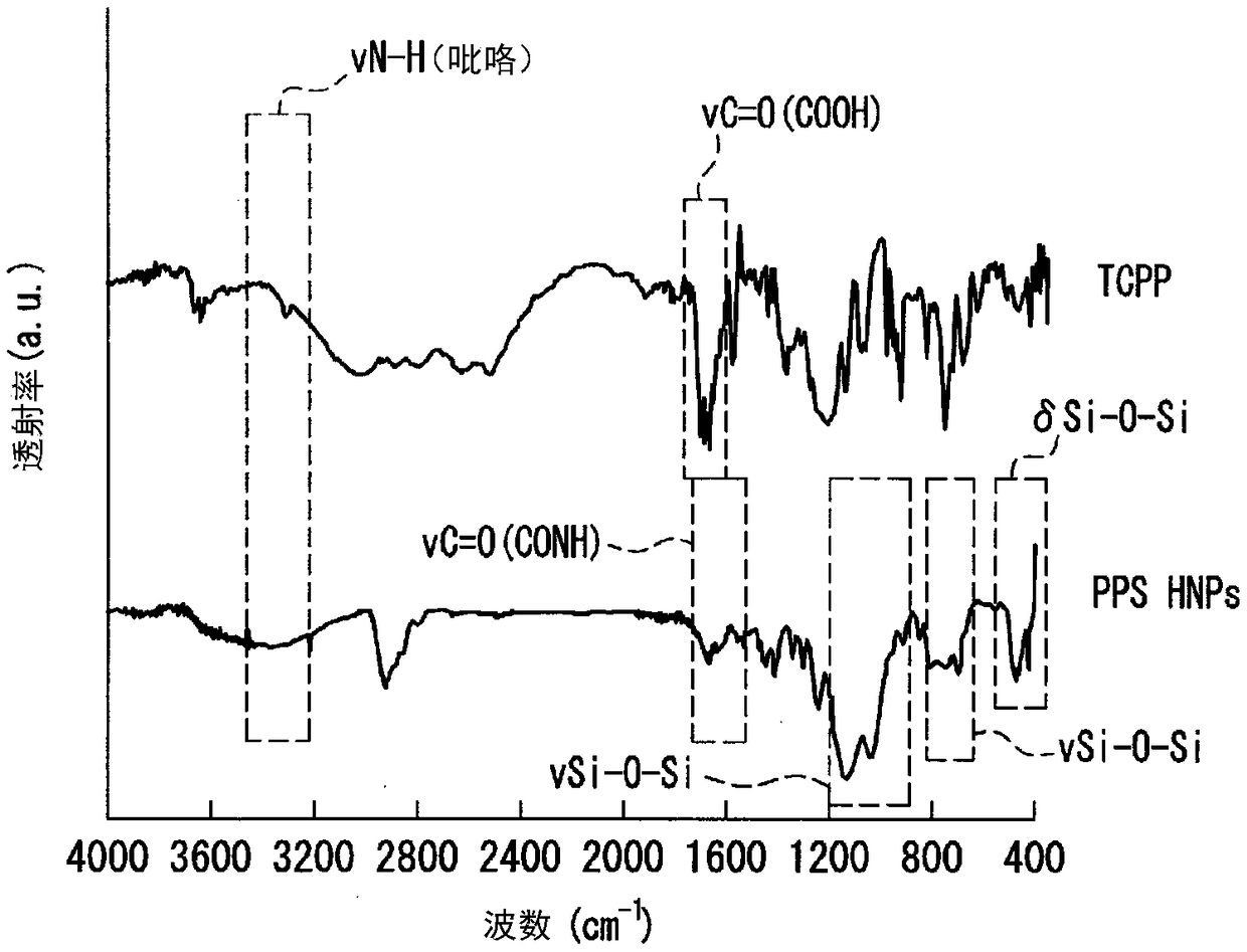
[0118] (1) APTES (462 μmol) was added to a DMF solution (3.8 mM, 32 mL) of TCPP obtained by dissolving TCPP in DMF, followed by N,N′-dipropylcarbodiimide (480 μmol) and N- Hydroxysuccinimide (480 μmol), stirred at 50° C. for 24 hours.
[0119] (2) 200 µL of the above-obtained porphyrin-silane DMF solution (0.75 µmol of porphyrin-silane) was mixed with 5 µL (0.027 mmol) of MPTMS. 500 μL of DMF and 300 μL of ammonia water (concentration: 28% by mass, pH 11) were added to the obtained mixed solution, and the reaction was carried out at 80° C. for 24 hours.
[0120] (3) After 24 hours, the product was recovered as a precipitate by centrifugation (15000 rpm, 20 minutes), washed with water and ethanol several times, and finally dispersed in 1 mL of water.
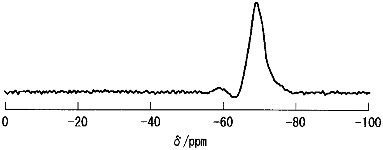
[0121] (4) The obtained substance is a compound of polysiloxane and porphyrin with polysiloxane as the carrier molecule, porphyrin as the fluorescent pigment a, covalently ...
Embodiment 2
[0127] (production of fluorescent probes)
[0128]
[0129] PPS HNPs were obtained in the same manner as in Example 1.
[0130]
[0131] (1) Add 251 μL of FA-PEG-Mal aqueous solution (concentration: 2 mg / mL, FA-PEG-Mal: 1.48×10 -4 mmol) and 63 μL of an aqueous solution of ICG-Mal (concentration: 2 mg / mL, ICG-Mal: 1.48×10 -4 mmol), stirred at 30°C for 3 hours.
[0132] (2) After the reaction, the product was recovered as a precipitate by centrifugation (15000 rpm, 20 minutes), washed with water several times, and finally dispersed in 1 mL of water.
[0133] (3) The obtained material is polysiloxane as the carrier molecule, porphyrin as the fluorescent pigment a, indocyanine green as the fluorescent pigment b, and folic acid as the cell surface binding substance. A complex (fluorescence probe) in which porphyrin, indocyanine green, and folic acid were bonded was measured by a dynamic light scattering method ("DelsaMax PRO" manufactured by Beckman Coulter), and it was a fl...
PUM
| Property | Measurement | Unit |
|---|---|---|
| wavelength | aaaaa | aaaaa |
| wavelength | aaaaa | aaaaa |
| particle size | aaaaa | aaaaa |
Abstract
Description
Claims
Application Information
 - R&D Engineer
- R&D Manager
- IP Professional
- Industry Leading Data Capabilities
- Powerful AI technology
- Patent DNA Extraction
Browse by: Latest US Patents, China's latest patents, Technical Efficacy Thesaurus, Application Domain, Technology Topic, Popular Technical Reports.
© 2024 PatSnap. All rights reserved.Legal|Privacy policy|Modern Slavery Act Transparency Statement|Sitemap|About US| Contact US: help@patsnap.com