
A power transmission base for a solar panel photovoltaic energy storage system

A solar panel and photovoltaic energy storage technology, applied in the field of power transmission base application and power transmission base, can solve the problem that installation, use or disassembly is not convenient and fast, the service life of solar energy and base is low, and the stability of cable transmission power is poor. and other problems to achieve the effect of reducing the vibration amplitude, improving the service life and avoiding direct contact

Active Publication Date: 2018-12-21
江阴鼎鑫铝业有限公司
View PDF7 Cites 4 Cited by
  • Summary
  • Abstract
  • Description
  • Claims
  • Application Information

AI Technical Summary

Problems solved by technology

[0004] The purpose of the present invention is to solve the high friction loss of the existing power transmission base used for solar panel photovoltaic energy storage system when it cooperates with the solar panel, and the cable used to transmit electric energy in the base is easy Intertwined with each other, the stability of the cable transmission power is poor, and when the solar panel encounters severe weather such as thunderstorms and strong winds, the base cannot provide shock absorption and buffering force for the solar panel, resulting in poor stability when the solar panel is working. The service life is low, and the installation, use or disassembly of the components of the base is not convenient and quick enough, so a power transmission base for solar panel photovoltaic energy storage system is proposed

Method used


Image

  • A power transmission base for a solar panel photovoltaic energy storage system
  • A power transmission base for a solar panel photovoltaic energy storage system
  • A power transmission base for a solar panel photovoltaic energy storage system

Examples


Embodiment Construction

[0030] The technical solutions of the present invention will be clearly and completely described below in conjunction with the embodiments. Apparently, the described embodiments are only some of the embodiments of the present invention, not all of them. Based on the embodiments of the present invention, all other embodiments obtained by persons of ordinary skill in the art without creative efforts fall within the protection scope of the present invention.

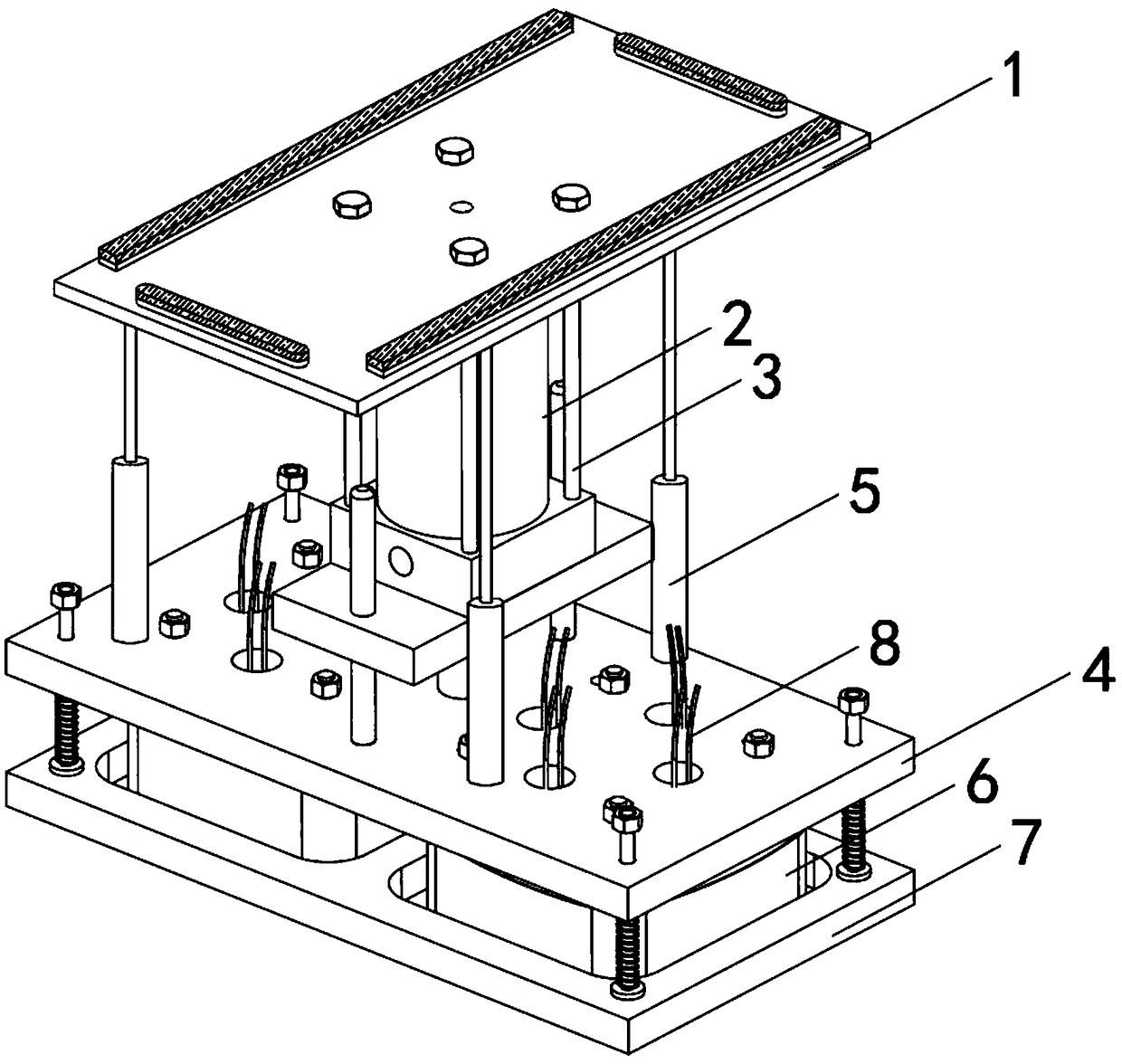
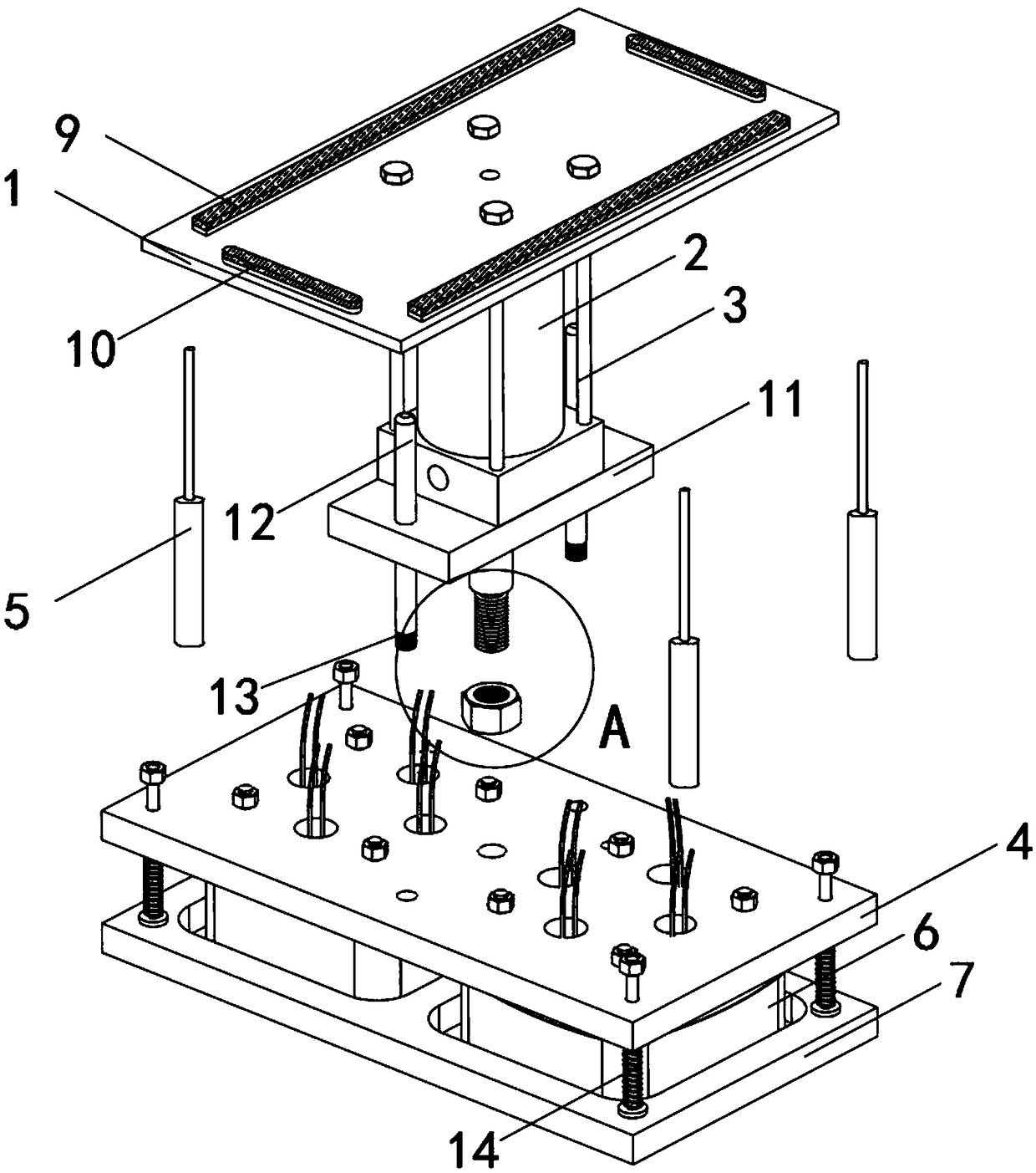
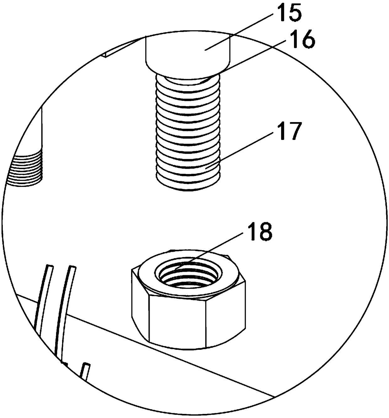
[0031] see Figure 1-7As shown, a power transmission base for a solar panel photovoltaic energy storage system includes an upper supporting plate 1, a supporting base 2, an inner supporting plate 4, a wire gathering base 6 and a lower supporting plate 7, and the supporting base 2 is vertically arranged on In the middle of the bottom of the upper supporting plate 1, an inner supporting plate 4 is vertically installed at the bottom of the supporting seat 2, and a lower supporting plate 7 is arranged parallelly below the inner...


PUM


Abstract

The invention discloses a power transmission base for a solar panel photovoltaic energy storage system, which comprises an upper bracket plate, a support seat, an inner bracket plate, a hub seat and alower bracket plate, wherein the support seat is vertically arranged in the middle of the bottom of the upper bracket plate, the bottom of the support seat is vertically installed with the inner bracket plate, the lower bracket plate is arranged below the inner bracket plate in parallel, and both ends of the inner bracket plate and the lower bracket plate are installed with the hub seat, and a cable tray is arranged in the hub seat. The invention has the advantages that: The extension rod on the retaining bracket at the four corners of the bottom of the upper bracket reduces the moving speedof the upper bracket through the friction between the inner rubber ring and the outer rubber ring, and cooperates with the third spring sleeve to reduce the shaking amplitude of the solar panel and its bracket, ensure the stability of the solar panel when working, and prolong the service life of the solar panel and the base; The base is firm and durable, has good social and economic benefits, andis suitable for popularization and use.

Description

technical field [0001] The invention relates to a base, in particular to a power transmission base used in a photovoltaic energy storage system of a solar panel, and belongs to the technical field of power transmission base applications. Background technique [0002] With the rapid development of people's living standards, photovoltaic solar panels are laid and used more and more frequently in people's lives. Solar panels convert solar energy into electrical energy, and store the electrical energy in the photovoltaic energy storage system through the power transmission base, which is convenient to use. Solar panels are a very green and environmentally friendly power generation equipment. [0003] On the one hand, the power transmission base plays the role of supporting and fixing the solar panel, and on the other hand, it stores electric energy in the photovoltaic energy storage system. There are still many shortcomings in the existing power transmission base for the solar p...

Claims


Application Information

Patent Timeline
Patent Type & Authority Applications(China)
IPC IPC(8): H02S10/20H02S20/00H02G3/04F24S25/12
CPCH02G3/045H02S20/00H02S10/20Y02E10/50Y02E70/30
Inventor 张晓曼
Owner 江阴鼎鑫铝业有限公司
Learn More