
A data query method, device and electronic equipment

A data query and to-be-queried technology, applied in the query field, can solve the problem of low development efficiency, and achieve the effect of meeting flexible and changing needs, improving work efficiency, and reducing workload

Active Publication Date: 2022-06-03
BEIJING QIYI CENTURY SCI & TECH CO LTD
View PDF4 Cites 0 Cited by
  • Summary
  • Abstract
  • Description
  • Claims
  • Application Information

AI Technical Summary

Problems solved by technology

[0004] However, the inventor found in the process of implementing the present invention that at least the following problems exist in the prior art: in the prior art, since the query SQL statement is pre-developed by the developer, in order to meet the flexible and changeable needs of users, it is necessary to Developers develop corresponding SQL statements for each potential query requirement, resulting in low development efficiency

Method used


Image

  • A data query method, device and electronic equipment
  • A data query method, device and electronic equipment
  • A data query method, device and electronic equipment

Examples


example 1

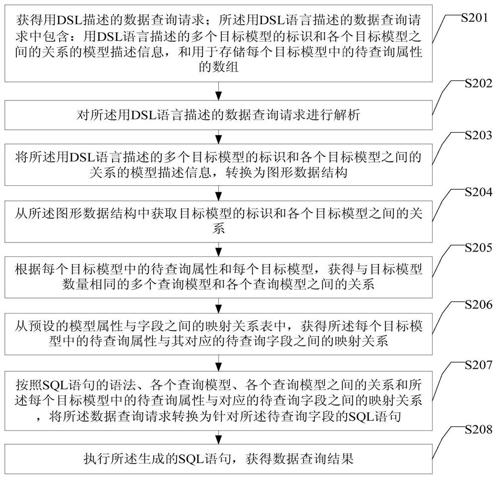
[0103] The data query request defined in DSL language is: query the name of each IDC (computer room) and the name of the Machine (server) in each IDC. Since the IDC (computer room) can contain multiple Machines (servers), the target model IDC and Machine are between. The relationship between is a one-to-many relationship, and the query result to be returned is in the form:

[0104] [["i.name"],["m.name"]]

[0105] Among them, IDC and Machine are the description information of the identification of each target model; the relationship between IDC and Machine is the model description information of the relationship between each target model; array [["i.name"], ["m.name" The name in ]] is the attribute to be queried in the target model IDC and Machine.

[0106] S202: Parse the data query request described in the DSL language.

[0107] In this step, the identifiers of multiple target models and the model description information of the relationship between each target model are ex...

example 2

[0202] If the data query request defined in the DSL language is: query the data whose name contains foobar in the target models ModelA, ModelB and ModelC.

[0203] Obtain the DSL data query request, and parse the query request into a graph as follows:

[0204]

[0205] b:Model B[name contains "foobar"];

[0206] c:Model C;

[0207] b~>@rel1~>a;

[0208] b~>@rel2~>c;

[0209] }

[0210] Node a is Type A

[0211] Type A{

[0212] name;

[0213] }

[0214] Node b is Type B

[0215] Type B{

[0216] name;

[0217] }

[0218] Node c is Type C

[0219] Type C{

[0220] name;

[0221] }

[0222] Among them, a, b and c are the target models ModelA, ModelB and ModelC, respectively, and the nodes in the converted graph. b~>@rel1~>c and b~>@rel2~>a respectively define node b and node c and The relationship between node b and node a, where rel1 and rel2 are the names of the relationship, and [name contains "foobar"] is a filter condition, which indicates that the query ...


PUM


Abstract

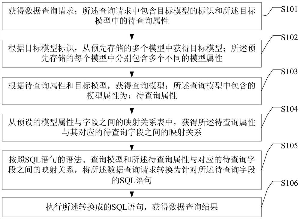
Embodiments of the present invention provide a data query method, device, and electronic equipment, which can obtain the target model ID and attributes to be queried according to the DSL data query request, obtain the target model from the pre-stored models according to the target model ID, and then Obtain the query model according to the attribute to be queried and the target model, and further, obtain the mapping relationship between the attribute to be queried and the corresponding field to be queried according to the preset mapping relationship table between the model attribute and the field, according to SQL The syntax of the statement converts the mapping relationship between the query model and the attribute to be queried and the corresponding field to be queried into an SQL statement, which realizes the automatic generation of the SQL statement, thereby effectively reducing the workload of developers and improving The work efficiency is improved, and since the developer does not need to directly write the SQL statement into the system, the risk of the SQL statement being injected with a virus, etc. is avoided, and the security of the system is improved.

Description

technical field [0001] The present invention relates to the technical field of query, in particular to a data query method, device and electronic device. Background technique [0002] Large Internet companies need to use various types of middleware services and underlying services to meet the needs of different users and provide better services. Whether it is a middleware service or an underlying service, there are many configuration items, and CMDB (Configuration Management Database) can be used to store and manage the configuration. The way to store configuration information is: developers create a model attribute table in the database, and then assign fields to each model attribute of the model, that is, define which column in the model attribute table stores which model attribute of the model, exemplarily, define Column 1 stores model attribute A, that is, assigns field column 1 to model attribute A; then stores the instantiated data of the model in the model attribute ...

Claims


Application Information

Patent Timeline
Patent Type & Authority Patents(China)
IPC IPC(8): G06F16/242
Inventor 章敏杰
Owner BEIJING QIYI CENTURY SCI & TECH CO LTD
Learn More