A Debris Flow Deposit Thickness Detection Method Based on Geological Radar Technology

A technology of geological radar and detection method, which is applied in the direction of measuring device, radio wave measurement system, radio wave reflection/reradiation, etc., can solve the problems of accuracy influence, thickness error of debris flow deposits, low detection accuracy, etc., to ensure The effect of accuracy and easy operation

Inactive Publication Date: 2020-08-07
CHINA UNIV OF GEOSCIENCES (BEIJING)
View PDF6 Cites 0 Cited by
  • Summary
  • Abstract
  • Description
  • Claims
  • Application Information

AI Technical Summary

Problems solved by technology

But its disadvantage is that it is relatively rough to detect the thickness of debris flow deposits only through sections and outcrops, and the larger the area of ​​debris flow accumulation area, the more inaccurate the thickness of deposits calculated by the geological sketch method
In addition, through the combination of remote sensing interpretation method and geological sketching method, the thickness change of debris flow deposits can be pre-estimated. During the process, the accuracy of the interpretation is often affected by the level and experience of the interpreters, so that there is a large error between the estimated value and the actual value of the thickness of the debris flow deposit, and the reliability is low.
The core drilling method can intuitively obtain the thickness of debris flow deposits in a small area, but its accuracy in the accumulation area is affected by the spacing and number of drill holes, and the high cost also limits the wide application of this method
Therefore, the conventional method of detecting the thickness of debris flow deposits has many shortcomings; first, there are many detection workflows, and the cost of manpower and material resources remains high; second, the quantitative value obtained by analysis is highly dependent on experience, so it must be Select personnel with rich work experience and a solid foundation; third, the detection accuracy is low, and it is difficult to provide fine data and reference for debris flow risk assessment

Method used


Image

  • A Debris Flow Deposit Thickness Detection Method Based on Geological Radar Technology
  • A Debris Flow Deposit Thickness Detection Method Based on Geological Radar Technology
  • A Debris Flow Deposit Thickness Detection Method Based on Geological Radar Technology

Examples


Embodiment

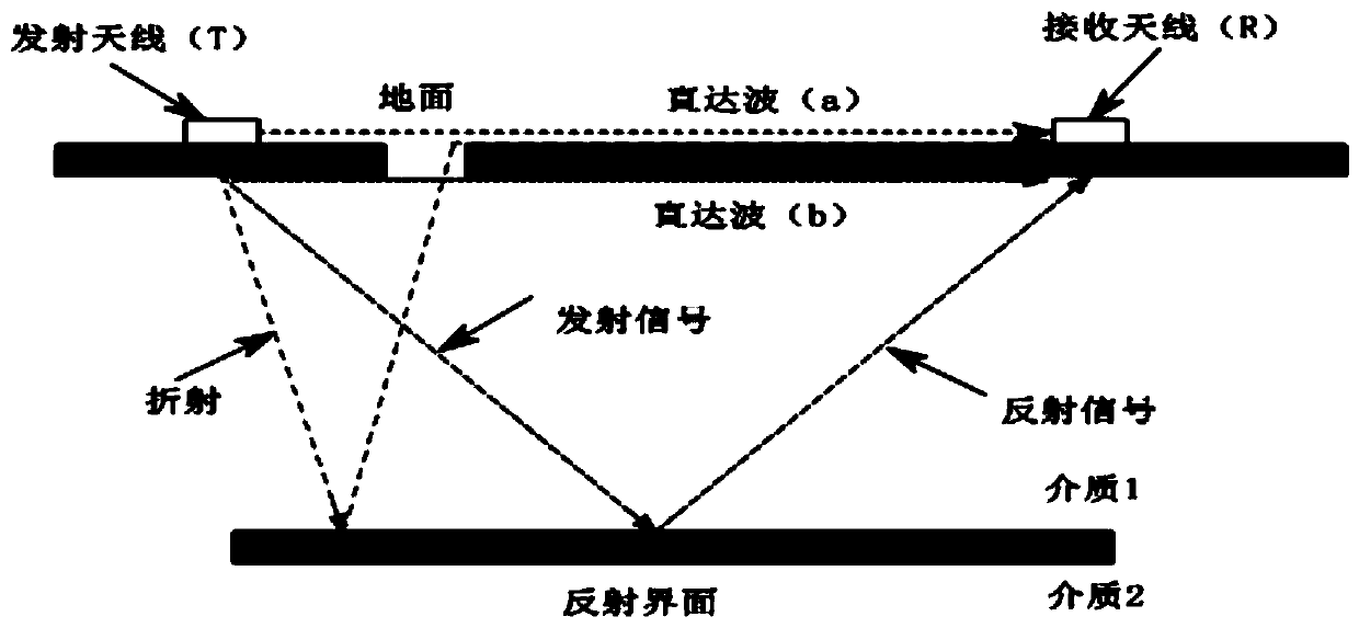
[0043] Such as Figure 1 to Figure 4 As shown, this embodiment provides a method for detecting the thickness of debris flow deposits based on geological radar technology. In this method, the following equipment is used: a 100MHz shielded antenna, a detection host, a computer terminal, and a lithium battery. Among them, at least two shielding antennas are configured, and they are composed of transmitting antennas and receiving antennas, which are used to transmit high-frequency electromagnetic pulse waves to debris flow deposits and receive high-frequency electromagnetic pulses reflected and / or refracted by debris flow deposits wave. The detection host is in communication connection with the shielding antenna, and is used to control the shielding antenna to emit high-frequency electromagnetic pulse waves, and to receive the high-frequency electromagnetic pulse waves reflected and / or refracted by the debris flow deposits fed back by the shielding antenna. The computer terminal a...


PUM


Abstract

The invention discloses a geological-radar-technology-based detecting method for thickness of debris flow accumulation, which comprises the following steps: laying a shielding antenna in the directionperpendicular to a debris flow channel; emitting high frequency electromagnetic pulse wave to debris flow accumulation by using the shielding antenna and using the shielding antenna to receive high frequency electromagnetic pulse wave reflected and / or refracted by the debris flow accumulation; transmitting the high frequency electromagnetic pulse wave reflected and / or refracted by the debris flowaccumulation to a detection main unit; carrying out a waveform treatment on the reflected and / or refracted high frequency electromagnetic pulse wave in a computer terminal; and dividing a waveform diagram corresponding to the treated waveform data to obtain the thickness of the debris flow accumulation. According to the above scheme, the invention has the advantages of simple detection, simple operation, cost saving, accurate detection and so on.

Description

Technical field [0001] The invention relates to the technical field of geological detection, in particular to a method for detecting the thickness of debris flow deposits based on geological radar technology. Background technique [0002] Debris flow is one of the main types of geological disasters. Debris flow disasters are widely developed in our country, and their causes are diverse. The calculation of the thickness of debris flow deposits formed in the history of debris flow basins has always been a difficult problem in debris flow risk assessment. Through fine detection of the thickness of debris flow deposits in history, it can provide important parameters and basis for the scientific evaluation of the impact range of debris flow and the comprehensive management of debris flow. [0003] At present, the existing methods for detecting the thickness of debris flow deposits mainly include geological sketching method, remote sensing interpretation method and core drilling method....

Claims


Application Information

Patent Timeline
Patent Type & Authority Patents(China)
IPC IPC(8): G01S13/88
CPCG01S13/885
Inventor 陈剑马传浩陈思华石倩
Owner CHINA UNIV OF GEOSCIENCES (BEIJING)
Why Eureka
Try Eureka