
Riverway depthkeeping water sample collection device and method

A technology for collecting devices and water samples, which is applied to the field of water sample collecting devices for river channel depth determination, can solve the problems of reading steel wire scale error, steel wire deviation, difficulty in quickly collecting water samples, etc., and achieves the effect of not easy to hold your breath.

Pending Publication Date: 2018-12-21
CHINA POWER CONSRTUCTION GRP GUIYANG SURVEY & DESIGN INST CO LTD
View PDF0 Cites 1 Cited by
  • Summary
  • Abstract
  • Description
  • Claims
  • Application Information

AI Technical Summary

Problems solved by technology

[0003] Most of the water sample collectors commonly used at present are connected to the water collector through simple steel wires with scale marks, and water samples are collected by adjusting the baffle switch. This method requires mechanical control of the depth of the collector, and due to the The effect leads to the deviation of the steel wire, which will cause a great error in reading the scale of the steel wire
Recently, some scholars have collected water samples in layers by automatically monitoring the depth of the water collector. This method has made some progress in collecting water samples at a set depth. However, due to the presence of air in the collector, this collection device , It is easy to hold your breath when taking water samples in the water, it is difficult to quickly collect water samples, and there is no specific instruction and mark to directly check the status of water sample collection

Method used


Image

  • Riverway depthkeeping water sample collection device and method
  • Riverway depthkeeping water sample collection device and method
  • Riverway depthkeeping water sample collection device and method

Examples


Embodiment Construction

[0026] The present invention will be described in detail below in conjunction with the accompanying drawings.

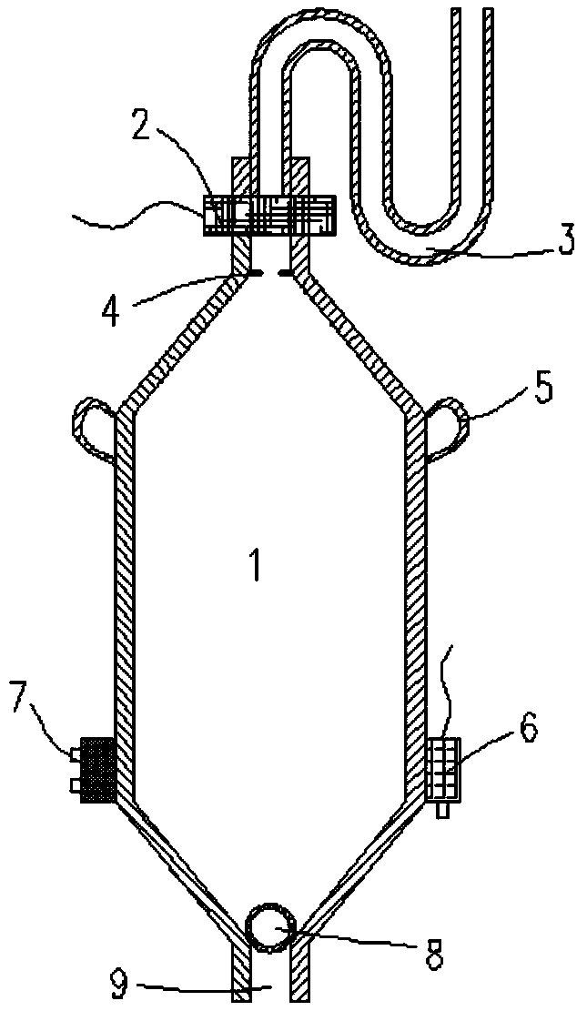
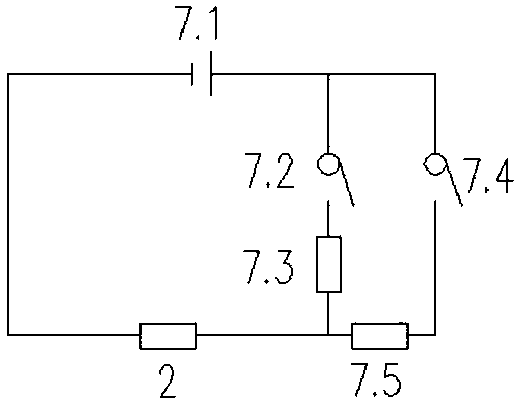
[0027] Such as Figure 1-3 As shown, the river course depth water sample collection device of the present invention comprises a sampling chamber 1, from figure 1 It can be seen that the cross-section of the sampling chamber 1 is hexagonal, similar to a capsule, and has a hollow structure with a chamber inside. Channel is water inlet 9. The upper end of the sampling chamber 1 is connected with the U-shaped pipe 3 through the solenoid valve 2, from figure 1 It can be seen from the figure that the U-shaped tube 3 is actually an S-shaped tube formed by connecting two sections of U-shaped tubes, and one end of the U-shaped tube 3 is connected to the connecting channel at the upper end of the sampling chamber 1 . A probe 4 is arranged between the electromagnetic valve 2 and the sampling chamber 1, and the probe 4 is located at the channel opening at the upper end of the...


PUM


Abstract

The invention discloses a riverway depthkeeping water sample collection device and method. The device comprises a sampling chamber of a hollow structure; a connection channel is arranged at the upperend of the sampling chamber to be connected with one end of a U-shaped pipe; a solenoid valve is arranged on the connection channel; a probe is arranged at a channel opening, positioned on one side ofthe inner cavity of the sampling chamber, of the connection channel; a pothook is installed at the upper part of the side edge of the sampling chamber, and a tester and a controller are arranged at the lower part of the side edge; a water inlet is formed in the bottom of the sampling chamber; and a floating ball is arranged in the sampling chamber. According to the device provided by the invention, the air outlet above the solenoid valve is dual-U-shaped; when the solenoid valve is opened, air in the sampling chamber can be discharged from the U-shaped pipe, and thus the device is not easy tohold the air. When no water enters the sampling chamber, the water inlet is sealed by the floating ball due to own gravity, after the water enters, the floating call can move upwards to reach the position of the probe so as to be connected with the probe to form an access, and the on and off of the solenoid valve are automatically controlled by the controller.

Description

technical field [0001] The invention relates to a device and method for collecting water samples for determining the depth of a river channel, and belongs to the technical field of water sampling. technical background [0002] With the rapid development of the economy and the improvement of people's living standards, people's awareness of environmental protection has been greatly improved. People's understanding of environmental protection has become more and more clear, and their feelings have become more and more intense. The research on environmental protection is constantly increasing. As an important basis for human survival, water resources play an important role in people's daily life and social development. A good analysis of the water quality of water resources is of great significance to the protection of water resources. Before water quality analysis Doing a good job in water sample collection is the top priority to ensure accurate water quality analysis results....

Claims


Application Information

Patent Timeline
Patent Type & Authority Applications(China)
IPC IPC(8): G01N1/10G01F23/70G01C13/00
CPCG01N1/10G01C13/008G01F23/703
Inventor 胡亚运陈仁宏肖蕾路雷
Owner CHINA POWER CONSRTUCTION GRP GUIYANG SURVEY & DESIGN INST CO LTD
Learn More