
Powder engine with adjustable flame stabilizer position and method for installing flame stabilizer of powder engine

A technology of engine and flame stabilizer, which is applied in the direction of powdered engine fuel, machine/engine, combustion engine, etc. It can solve the problems that the position of the stabilizer cannot be adjusted freely, the refilling of closed fuel is inconvenient, and the consumption of materials, etc., to achieve practicality and Easy to adjust, simple structure, improved effect

Active Publication Date: 2018-12-21
NANJING UNIV OF SCI & TECH
View PDF6 Cites 3 Cited by
  • Summary
  • Abstract
  • Description
  • Claims
  • Application Information

AI Technical Summary

Problems solved by technology

The fluidization device of the existing powder engine realizes adjustable thrust, but fuel needs to be filled in the storage tank in advance, and the closedness of the structure brings inconvenience to refilling the fuel. filling, therefore, the optimization of the powder engine fluidized powder supply device is very necessary
In order to improve the combustion efficiency of fuel powder in the engine, it is necessary to install a flame stabilizer (flame stabilizer) in the combustion chamber, and the flame stabilizer of the existing device is welded to a fixed position on the screw rod, and the position of the stabilizer cannot be adjusted freely. To meet the requirements of different working conditions, it takes a lot of material to weld the flame stabilizer to different positions on the screw, resulting in a large consumption of materials

Method used


Image

  • Powder engine with adjustable flame stabilizer position and method for installing flame stabilizer of powder engine
  • Powder engine with adjustable flame stabilizer position and method for installing flame stabilizer of powder engine
  • Powder engine with adjustable flame stabilizer position and method for installing flame stabilizer of powder engine

Examples


Embodiment Construction

[0035] In order to better understand the technical content of the present invention, specific embodiments are given and described as follows in conjunction with the accompanying drawings.

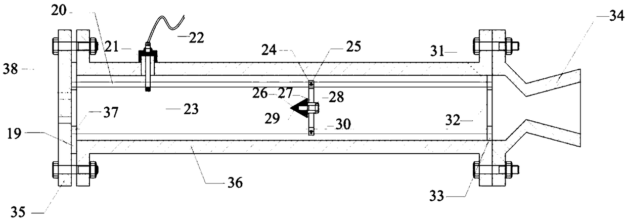
[0036] combine figure 1 , a powder engine with adjustable flame stabilizer position, said engine comprises a powder fuel supply device, a powder oxidant supply device, a combustion chamber 36 and a nozzle 34, and said powder fuel supply device and a powder oxidizer supply device are connected to the combustion chamber 36 The front end of the combustion chamber 36 is respectively connected with the front end of the combustion chamber 36 through the pipeline 39, and the rear end of the combustion chamber 36 is connected with the nozzle pipe 34, and the flame stabilizer 29 is arranged in the combustion chamber 36, and the flame stabilizer 29 is in the The axial position in the combustion chamber 36 can be adjusted.

[0037]Further, the combustion chamber 36 is fixed with M metal slide rails 2...


PUM


Abstract

The invention provides a powder engine with an adjustable flame stabilizer position and a method for installing a flame stabilizer of the powder engine. The engine comprises a powder fuel supplying device, a powder oxidizing agent supplying device, a combustion chamber 36 and a spraying pipe 34, wherein the powder fuel supply device, the powder oxidant supply device and the combustion chamber 36 are connected with the front end of the combustion chamber 36 through pipelines, the rear end of the combustion chamber 36 is connected with the spraying pipe 34, a flame stabilizer 29 is arranged in the combustion chamber 36, and the axial position of the flame stabilizer 29 in the combustion chamber 36 can be adjusted. The position of the flame stabilizer is adjustable, and the axial position ofthe flame stabilizer can be adjusted according to the requirements of different operating conditions of the engine, so that more sufficient combustion of fuel can be realized, and a detachable fixingdevice of the flame stabilizer is simple in structure, practical and convenient to adjust.

Description

technical field [0001] The invention belongs to the technical field of powder rocket engines, and in particular relates to a powder engine with an adjustable flame stabilizer position and an installation method for the flame stabilizer. Background technique [0002] Al / AP (aluminum / ammonium perchlorate) powder rocket engine is a rocket engine that uses ultra-fine aluminum powder as fuel and ammonium perchlorate as oxidant. The powder engine includes two fuel fluidization supply sections and fuel combustion sections. In the part, the powder in the storage tank is sent into the combustion chamber by piston propulsion and high-speed airflow, and the combustion is stable under the turbulence of the flame stabilizer. Effect. Al / AP powder rocket motor can carry oxidant and fuel, so it can work in vacuum, and has a good application prospect in the field of aerospace. [0003] The powder supply technology is one of the key technologies of the Al / AP powder rocket engine. The contin...

Claims


Application Information

Patent Timeline
Patent Type & Authority Applications(China)
IPC IPC(8): F02B45/04F02B23/00
CPCF02B23/00F02B45/04Y02T10/12Y02T10/30
Inventor 白桥栋李旺
Owner NANJING UNIV OF SCI & TECH
Learn More