A device for high strain test of cast-in-situ pile and its manufacturing method

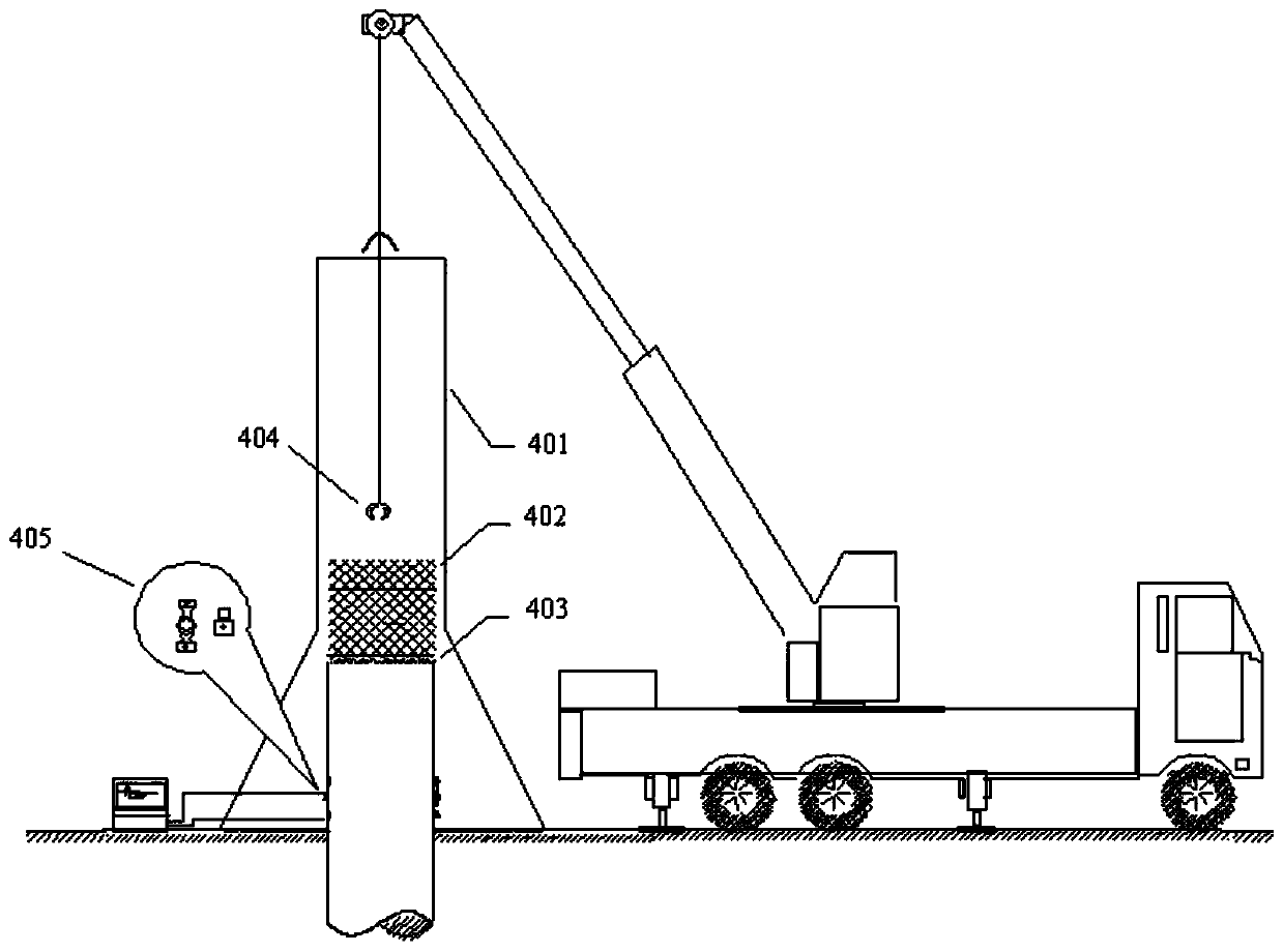
A manufacturing method and high-strain technology, which can be applied in the test of foundation structure, construction, foundation structure engineering, etc., can solve the problems of heavy weight, secondary impact of pile body, collision of guide frame 401, etc., so as to reduce safety hazards and operating costs , to avoid the secondary impact, to ensure the effect of precision

Active Publication Date: 2020-05-01
CHINA MCC20 GRP CORP
View PDF7 Cites 0 Cited by
  • Summary
  • Abstract
  • Description
  • Claims
  • Application Information

AI Technical Summary

Problems solved by technology

[0004] (1) The guide frame 401 generally has a height of 4-6m and a weight of 2-3T. Due to its large size and heavy weight, it increases the difficulty of transportation and testing;
[0005] (2) After the heavy hammer 402 impacts the pile body, it is easy to collide with the guide frame 401, causing a secondary impact on the pile body and affecting the collection of data signals;
[0006] (3) During the test, a crane is required to lift the weight 402, which increases the potential safety hazards and functional costs during the test

Method used


Image

  • A device for high strain test of cast-in-situ pile and its manufacturing method
  • A device for high strain test of cast-in-situ pile and its manufacturing method
  • A device for high strain test of cast-in-situ pile and its manufacturing method

Examples


Embodiment Construction

[0039] The present invention will be further described below in conjunction with the accompanying drawings and specific embodiments, so that those skilled in the art can better understand the present invention and implement it, but the examples given are not intended to limit the present invention.

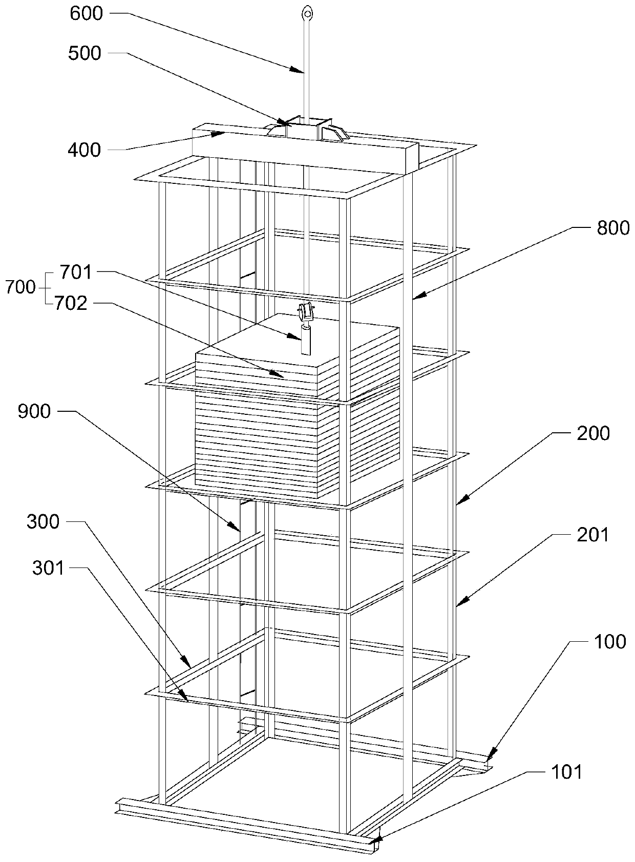
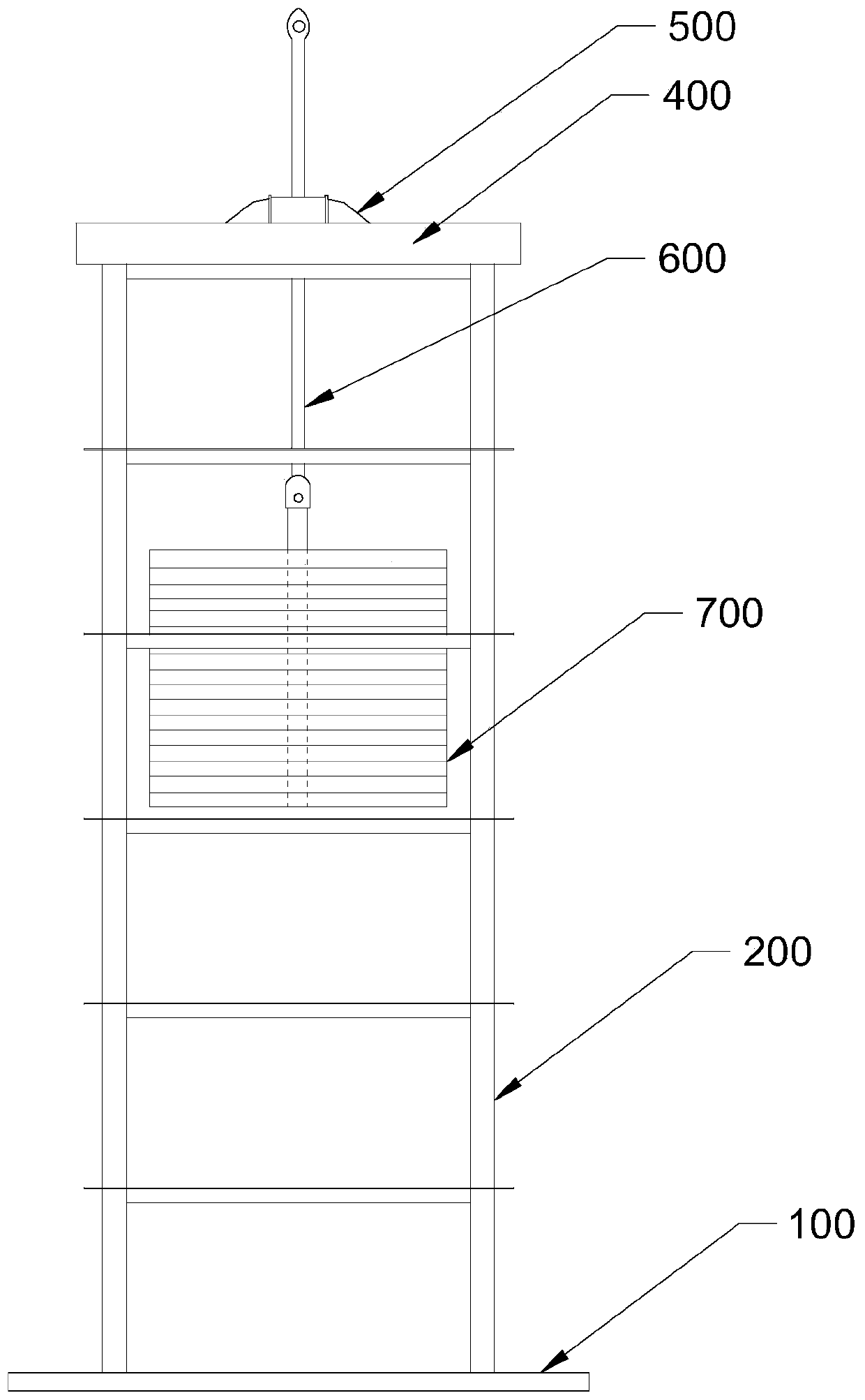
[0040] A device for high strain testing of cast-in-situ piles, such as Figure 2~5 shown, including:

[0041] A bottom beam assembly 100 is connected by four bottom beams 101 to form a "mouth" shape;

[0042] A vertical beam assembly 200, comprising four vertical beams 201, each of which is fixed to the junction of two bottom beams 101;

[0043] Multiple beam assemblies 300, each beam assembly 300 includes: four beams 301 on the same plane, each beam 301 is connected between two vertical beams 201 and is perpendicular to the vertical beams 201 , a plurality of the beam assemblies 300 are arranged along the elongation direction of the vertical beam 201;

[0044] A top beam 400, ...


PUM


Abstract

The invention provides a device for a high-strain test of a cast-in-place pile and a manufacturing method of the device. The device comprises a clamping assembly which is arranged above a top beam. The clamping assembly comprises a first abutting plate, a second abutting plate, a first clamp, a second clamp and a hydraulic oil cylinder, and the first abutting plate and the second abutting plate are arranged on the two sides of a hole, are perpendicular to the upper surface of the top beam and are fixed to the top beam. The first clamp and the second clamp are arranged between the first abutting plate and the second abutting plate and located on the two sides of the hole, the first clamp is fixed to the first abutting plate, and the hydraulic oil cylinder is fixed to the second abutting plate. The second clamp is fixed to the end of an ejector rod of the hydraulic oil cylinder, the first clamp and the second clamp are located in the telescopic direction of the ejector rod of the hydraulic oil cylinder, and a clamping part is formed between the first clamp and the second clamp when the first clamp and the second clamp are combined. The device is of a framework structure, the weight is reduced, the transportation and testing difficulty is reduced, use of a crane in the test is reduced, and potential safety hazards and the operation cost are reduced.

Description

technical field [0001] The invention relates to the technical field of building construction, in particular to a device for high strain test of cast-in-situ piles and a manufacturing method thereof. Background technique [0002] The detection of foundation pile height strain method is to apply an impact force on the top of the pile in the axial direction, so that the pile has sufficient penetration, and measure the response of the resulting pile mass stress and acceleration. Through wave theory analysis, it is judged that the single pile is vertical. Testing methods for axial compressive bearing capacity and pile integrity. [0003] This test method needs to apply a certain impact force on the top of the pile along the pile body. At present, it is usually carried out by using a heavy hammer and a guide frame. See figure 1 . The heavy hammer 402 is used to cooperate with the guide frame 401. It is necessary to use a crane to lift the heavy hammer 402 to a certain height, an...

Claims


Application Information

Patent Timeline
Patent Type & Authority Patents(China)
IPC IPC(8): E02D33/00
CPCE02D33/00
Inventor 朱松苏欣崔松明方吉唐春乐
Owner CHINA MCC20 GRP CORP
Why Eureka
Try Eureka