
Temperature control method for concrete high arch dam in severe cold area

A high arch dam and concrete technology, applied in construction, infrastructure engineering and other directions, can solve the problems of difficult to ensure the safety of the dam body, the influence of the integrity of the dam body, and the difficulty of quality assurance, so as to simplify the temperature control measures and solve the problem of temperature control. Problems, simple and fast construction effect

Inactive Publication Date: 2018-12-21
CHINA WATER RESOURCES BEIFANG INVESTIGATION DESIGN & RES
View PDF2 Cites 4 Cited by
  • Summary
  • Abstract
  • Description
  • Claims
  • Application Information

AI Technical Summary

Benefits of technology

This technology simplifies the process for controlling temperatures during building constructions that use concrete or other materials instead of conventional methods like steel bars. It also improves structural stability without requiring specialized heat fields at extreme locations such as those near water sources where heavy rain can damage these structures over time. Overall this results in improved durability and reduced costs associated with constructing high-arch buildings under harsh conditions.

Problems solved by technology

This patents describes various technical problem addressed by this patented technology relating to improving the durability and lifespan of building materials used at extreme temperatures such as those found near coastal environments or harsh winter conditions where they may experience freeze/thaw cycles that can cause damage over time due to their thermal expansion properties. Temperature loading plays a crucial role because its impact depends upon factors like ambient moisture content (SCA) levels, groundwater level, soil compaction characteristics, and other environmental variables. To address these issues, there have been developed methods involving controlling the temperature inside the curved section of buildings called hot box concretes (HCC). These techniques involve placing vertically placed metal blocks within the HCS while maintaining constant pressure applied through hydraulic cylinders. By adjusting the amount of material added into each block, the resulting temperature gradient caused by gravity effects can be minimized without causing excessive strain on the restoring force of the brick itself. Additionally, the use of protective measures against potential failure modes helps keep the entire structure intact even if any cracks occur. Overall, the goal of optimizing temperature management solutions involves ensuring proper protection of structures exposed to extremely challenging weather conditions.

Method used


Image

  • Temperature control method for concrete high arch dam in severe cold area

Examples


Embodiment Construction

[0011] Below in conjunction with accompanying drawing and specific embodiment the present invention is described in further detail:

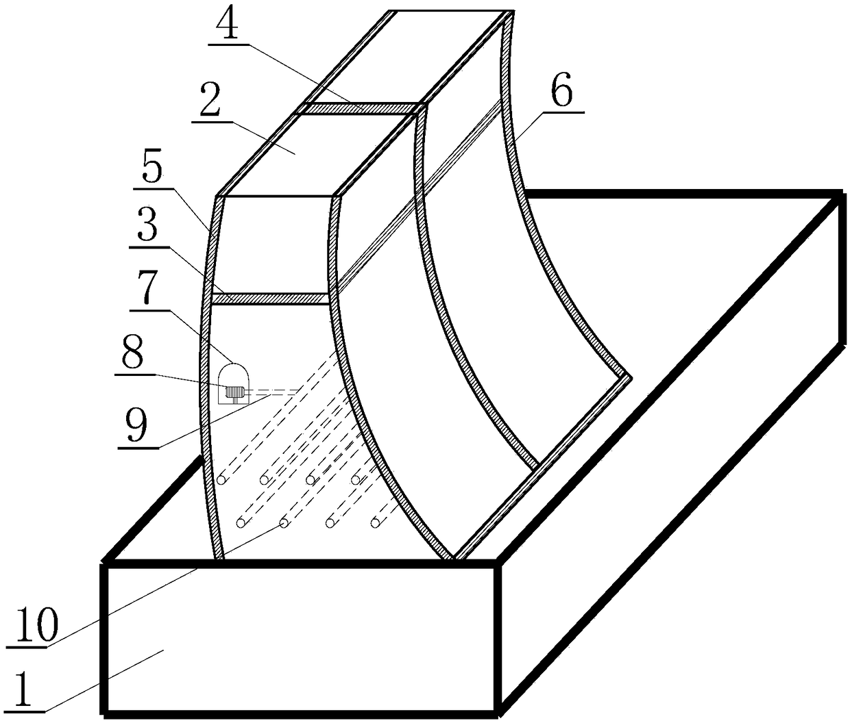
[0012] Such as figure 1 As shown, the temperature control method of the concrete high arch dam in the severe cold area of ​​the present invention, the high arch dam body 2 poured on the bedrock 1 is provided with horizontal joints 3 and vertical joints 4, and the construction period is followed by the construction of the high arch dam body 2 The upstream thermal insulation layer 5 is arranged on the upstream side of the dam body, and the downstream thermal insulation layer 6 is arranged on the downstream side. A corridor 7 is arranged in the dam body 2 of the high arch dam, and a water supply pump 8 is arranged in the corridor 7. The thermal insulation water pipes 10 buried in the serpentine arrangement at the contact position between the dam body 2 and the bedrock 1 of the high arch dam pass water to raise the temperature, so as to maintain a r...


PUM


Abstract

The invention discloses a temperature control method for a concrete high arch dam in a severe cold area. A high arch dam body poured on a bedrock is provided with a horizontal joint and a vertical joint; and during the construction period, along with pouring of the high arch dam body, the upstream side of the dam body is provided with an upstream side insulation layer, the downstream side of the dam body is provided with a downstream side insulation layer, a corridor is arranged in the high arch dam body, a water supply pump is arranged in the corridor, and the water supply pump supplies waterthrough a water supply pipe to an S-shaped heat preservation water pipe embedded into the position, in contact with the bedrock, of the high arch dam body to rise the temperature, and a higher temperature field of the dam body is maintained. The temperature control problem is solved, construction is simple and fast, the construction period is shortened, and immeasurable economic benefits and safety guarantee to construction of high arch dam in the severe cold area are obtained.

Description


Claims


Application Information

Patent Timeline
Owner CHINA WATER RESOURCES BEIFANG INVESTIGATION DESIGN & RES
Learn More