


Quick Research
Generate reliable direction feasibility study reports for your R&D in just a few steps.

Technical Q&A
Discover and master advanced knowledge NOW. Basics, ideas, possibilities, all at once.

Find Solutions
As an expert in R&D theories, this can generate solutions to your technical problems instantly.

Evaluate Feasibility
Analyze your overall solution with one click, know your potential R&D risks in advance.

Monitor Landscape
Get weekly tech updates, stay abreast of the latest tech innovations and key insights.
Wall forming machine for continuous cement-soil interlocking pile retaining wall of foundation pit
A cement-soil and wall-forming machine technology, which is applied to sheet pile walls, earth movers/excavators, earth square drilling and mining, etc. It can solve the problems that the drill pipe cannot be drilled, and the adaptability to different soil environments is not strong.
- Summary
- Abstract
- Description
- Claims
- Application Information
AI Technical Summary
Problems solved by technology
Method used
Image

Examples
Embodiment 1
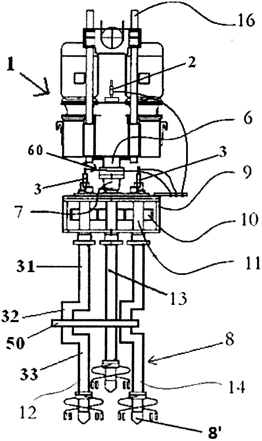
[0033] Such as figure 2 As shown, the wall-forming machine for the continuous cement-soil occlusal pile retaining wall of the foundation pit in this embodiment includes: a power unit 1, which is provided with an air injection port 2 and a water injection port 3; a drill rod mechanism 8, and The power unit is connected, wherein the drill rod mechanism 8 is used to form a plurality of interconnected continuous pile holes at one time, wherein the drill rod mechanism includes a plurality of drill rods, and in this embodiment, the drill rod mechanism The rod is specifically the first drill rod 12, the second drill rod 13 and the third drill rod 14, and the drill bit 8' positioned at the bottom of the drill rod; Air pipe (not marked here), the upper ends of the grouting pipe and the gas injection pipe are connected to the water injection port and the gas injection port respectively, and the lower ends of the grouting pipe and the gas injection pipe are connected to the drill Rod c...
Embodiment 2
[0042] Such as Figure 8 As shown, the difference between the wall-forming machine for the continuous cement-soil occlusal pile retaining wall of the foundation pit of this embodiment is that two drill pipes that are synchronous and rotate in the same direction are provided with at least two The curved section, and the first device is installed on the corresponding curved sections of the two drill rods. The above design can realize that the first device is provided at more than two positions of the drill pipe above and below, which increases the one-time damage width to the protrusion of the soil body, thereby realizing the fast drilling of the drill pipe. It can better destroy the protrusion of the soil. Such as Figure 9 As shown, the curved segments may not bend in the same direction. The above design can realize that the first device is provided at more than two positions of the drill pipe above and below, which increases the one-time damage width to the protrusion of t...
Embodiment 3
[0044] Such as Figure 10 As shown, the difference between the wall-forming machine for the continuous cement-soil occlusal pile retaining wall of the foundation pit of this embodiment compared with the above-mentioned embodiment 1 is that: two drill pipes that are synchronous and rotate in the same direction are provided with a said a curved section, and the first device is jointly installed on the corresponding curved sections of the two drill rods. In addition, the curved section has two curved portions with an inclination angle of 45 degrees and opposite inclination directions. Such as Figure 11 As shown, the drill rod of the wall-forming machine used for the continuous cement-soil occlusal pile retaining wall of the foundation pit can have two above-mentioned curved sections of the present embodiment, as Figure 12 As shown, the drill rod of the wall forming machine used for the continuous cement-soil occlusal pile retaining wall of the foundation pit can have two abov...
PUM
 Abstract
Description
Claims
Application Information
 - R&D Engineer
- R&D Manager
- IP Professional
- Industry Leading Data Capabilities
- Powerful AI technology
- Patent DNA Extraction
Browse by: Latest US Patents, China's latest patents, Technical Efficacy Thesaurus, Application Domain, Technology Topic, Popular Technical Reports.
© 2024 PatSnap. All rights reserved.Legal|Privacy policy|Modern Slavery Act Transparency Statement|Sitemap|About US| Contact US: help@patsnap.com