
A display control layout adjustment system

A layout adjustment and display device technology, applied in the field of avionics systems, can solve the problems of inability to realize rapid adjustment of display and control layout, long iteration cycle, high iteration cost, etc., and achieve the effect of shortening iteration cycle, reducing iteration cost, and rapid adjustment

Inactive Publication Date: 2018-12-21
BEIJING AERONAUTIC SCI & TECH RES INST OF COMAC +1
View PDF6 Cites 4 Cited by
  • Summary
  • Abstract
  • Description
  • Claims
  • Application Information

AI Technical Summary

Problems solved by technology

[0025] The purpose of this application is to provide a display and control layout adjustment system, which adjusts the layout of the display device and the control device by controlling the movable bracket mechanism by the control device, which solves the problem that the rapid adjustment and targeted adjustment of the display and control layout cannot be realized in the prior art. Research on the impact of "display and control layout" on ergonomics, and at the same time solve the problem that traditional civil aircraft cockpit design requires a long iteration cycle and high iteration cost

Method used


Image

  • A display control layout adjustment system
  • A display control layout adjustment system
  • A display control layout adjustment system

Examples


Embodiment 1

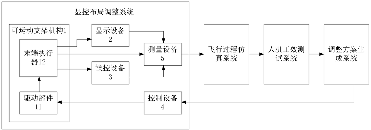
[0049] figure 1 It is a schematic composition diagram of the display and control layout verification and optimization platform provided in Embodiment 1 of the present application.

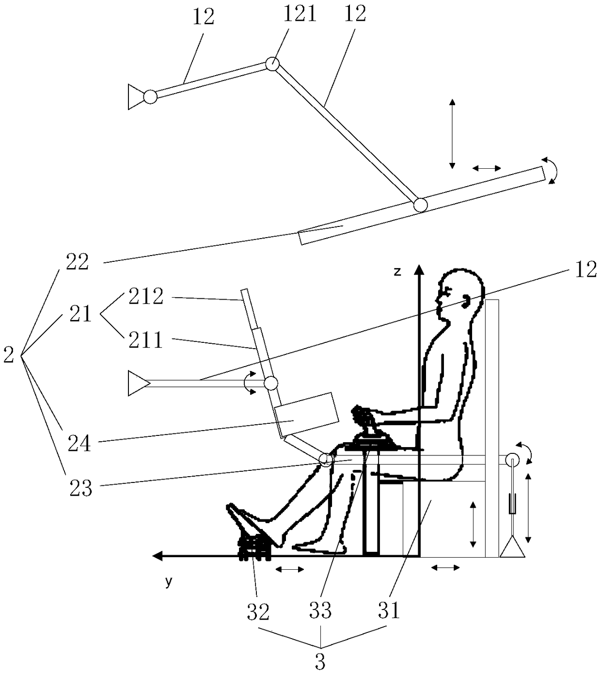
[0050] figure 2 It is a schematic structural diagram of the display and control layout adjustment system provided in Embodiment 1 of the present application.

[0051] Please refer to figure 1 , figure 2 , this embodiment provides a display and control layout adjustment system, including: a movable bracket mechanism 1 , a display device 2 , a manipulation device 3 and a control device 4 .

[0052] The movable support mechanism 1 includes a driving part 11 and a plurality of end effectors 12 connected to the driving part 11 , and each end effector 12 is provided with a movable joint 121 .

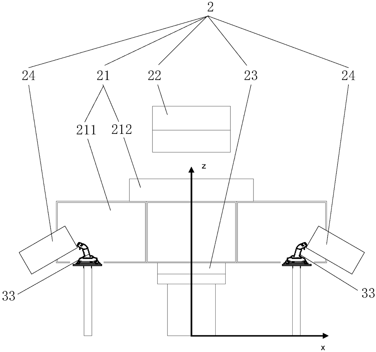
[0053] The display device 2 includes multiple panels, and each panel is connected to at least one end effector 12 .

[0054] The control device 3 includes two driver's seats 31 and pedals 32 , and the drive...

Embodiment 2

[0093] The difference between this embodiment and Embodiment 1 is that the movable support mechanism 1 is an active structure, and the power source of the driving part 11 is a steering gear or a motor with signal feedback, and the movable joint 121 is driven and controlled by automatic control. move and hold at the preset position. Specifically, when the movable support mechanism 101 is an active structure, the driving part 11 is driven by a steering gear or a motor with signal feedback, so that all movable joints 121 on the end effector 12 have the ability to actively run and brake.

[0094] The structure, composition and connection relationship of other parts in this embodiment are the same as those in Embodiment 1, and will not be repeated here.

Embodiment 3

[0096] The difference between this embodiment and Embodiment 1 is that the movable support mechanism 1 is a passive structure, the power source of the driving part 11 is artificial, and the movable joint 121 is adjusted to a preset position through manual control, and the lock, buckle, The latch or the friction plate is locked to realize the passive operation and braking of the movable joint 121 . Specifically, in this embodiment, all the movable joints 121 on the end effector 12 do not have the ability to actively run and brake, and need to be operated and braked manually by the operator.

[0097] The structure, composition and connection relationship of other parts in this embodiment are the same as those in Embodiment 1, and will not be repeated here.


PUM


Abstract

A display and control layout adjustment system comprises a movable bracket mechanism (1) comprising a driving member (11) and a plurality of end effectors (12) connected thereto; A display device (2)includes a plurality of panels, each panel being connected to at least one end effector (12); A manipulating device (3), a driver seat (31) and a pedal (32) of the manipulating device (3) are respectively connected with an end effector (12); A control device (4) for controlling the movement of the movable bracket mechanism (1) according to a layout adjustment command; The movable bracket mechanism(1) drives the display device (2) and the manipulation device (3) to move under the control of the control device (4) for layout adjustment. The layout adjustment system of the present application realizes the quick adjustment of the display and control layout, and at the same time can greatly shorten the iterative period of the cockpit design and reduce the iterative cost.

Description

technical field [0001] The present application relates to the technical field of avionics systems, in particular to a display and control layout adjustment system. Background technique [0002] The cockpit is the main working environment for the pilot to perform flight operations, and it is also the main place for the pilot to interact with the aircraft. The cockpit design results will directly affect the pilot's operating comfort, and further affect the driving safety and reliability. The internal functional modules of the contemporary mainstream civil aviation cockpit include but are not limited to: avionics display control system (partially integrated with electronic flight bag), multi-electric control and control load system, circuit breaker and fire protection device, etc., among which the display control system is the main component of the cockpit. Functional equipment is the main medium for pilots to obtain aircraft operation data, grasp the aircraft situation and pr...

Claims


Application Information

Patent Timeline
IPC IPC(8): B64D43/00
CPCB64D43/00
Inventor 曾锐张炯樊谕涵蒋欣
Owner BEIJING AERONAUTIC SCI & TECH RES INST OF COMAC
Learn More