
Workpiece machining tool

A machining and workpiece technology, applied in the field of machining tooling of workpieces, can solve the problems of difficult to ensure the dimensional accuracy of workpieces, prone to vibration knives, spring knives, and less force support of end plates, and reduce the clamping and correction time. Fast installation speed and stable clamping effect

Pending Publication Date: 2018-12-21
无锡市航鹄精密机械有限公司
View PDF4 Cites 3 Cited by
  • Summary
  • Abstract
  • Description
  • Claims
  • Application Information

AI Technical Summary

Problems solved by technology

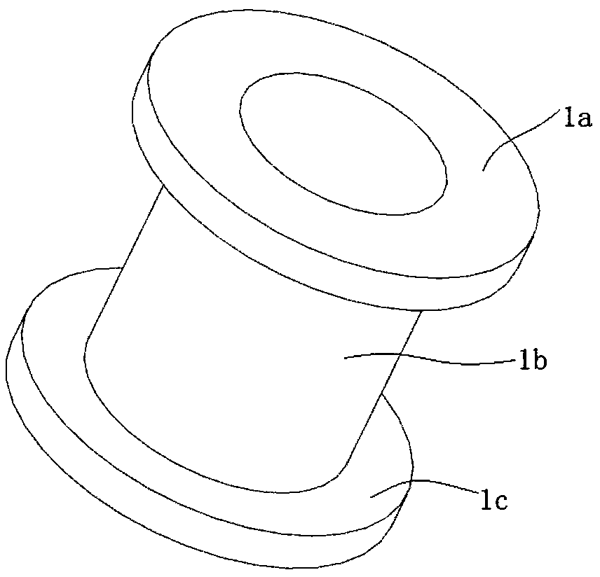
[0002] as attached figure 1 As shown, a rough-machined workpiece in the shape of an "I" includes a shaft body 1b and ring-shaped end plates 1a and 1c integrally arranged at both ends of the shaft body 1b. The two ring-shaped end plates contain a plurality of Processing features, such as shape processing, outer contour processing, milling notch and drilling, etc., the existing processing tooling uses a boss-shaped cylindrical structure, and the protruding boss part is pierced in the shaft body 1b. Then one of the ring-shaped end plates is fixed by means of a pressure plate and locking screws, and then the other end plate is milled. Although the processing tooling of this method is simple, but because the end plate to be processed is less supported by force, it causes its clamping Unstable, prone to tool vibration and bounce during processing, affecting the appearance of the workpiece, and it is not easy to ensure the dimensional accuracy of the workpiece, and even needs to be reworked continuously with empty tools, and in order to reduce the impact of the bounce tool, it is necessary to reduce the cutting speed, indirect The impact of the overall processing speed, resulting in reduced efficiency

Method used


Image

  • Workpiece machining tool
  • Workpiece machining tool
  • Workpiece machining tool

Examples


Embodiment Construction

[0017] The present invention will be further described below in conjunction with the accompanying drawings.

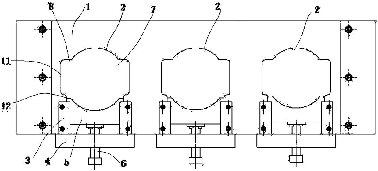
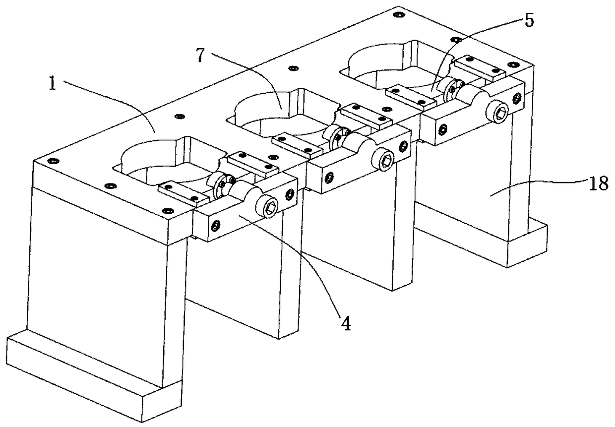
[0018] as attached figure 2 And attached image 3 As shown, a machining tool for a workpiece includes a base plate 1, the base plate 1 is a rectangular plate body, and a number of support plates 18 are arranged at the bottom of the base plate for supporting the base plate 1, and the base plate 1 includes at least one processing station 2. Each processing station correspondingly clamps a workpiece to be processed. The processing station 2 includes a clamping plate 5 and a driving mechanism 6. The clamping plate is a plate structure. The upper and lower parts of the substrate 1 are provided with The installation groove 7, one side of the installation groove 7 is an opening, the installation groove 7 is a U-shaped semi-closed structure, and the side wall opening in a length direction of the substrate 1 forms the opening side of the installation groove 7, so The opening...


PUM


Abstract

The invention discloses a workpiece machining tool. The workpiece machining tool comprises a base plate, at least one machining station is arranged on the base plate, the machining stations comprise clamping plates and driving mechanisms, the base plate is provided with mounting grooves in an up-down penetrating mode, one sides of the mounting grooves are provided with openings, clamping plates are arranged on the opening sides of the mounting grooves, and the clamping plates are arranged on the base plate in a sliding mode; and the driving mechanisms are arranged on the base plate, moreover,the driving mechanisms drive the clamping plates to slide in the mounting grooves in a reciprocating mode, and the clamping plates and the mounting grooves form closed-loop clamping and positioning holes. The workpiece machining tool can stably clamp workpieces, the influence of an elastic knife is reduced, and the machining precision and the machining efficiency are ensured.

Description

technical field [0001] The invention belongs to the field of machining tooling, in particular to a tooling for machining workpieces. Background technique [0002] as attached figure 1 As shown, a rough-machined workpiece in the shape of an "I" includes a shaft body 1b and ring-shaped end plates 1a and 1c integrally arranged at both ends of the shaft body 1b. The two ring-shaped end plates contain a plurality of Processing features, such as shape processing, outer contour processing, milling notch and drilling, etc., the existing processing tooling uses a boss-shaped cylindrical structure, and the protruding boss part is pierced in the shaft body 1b. Then one of the ring-shaped end plates is fixed by means of a pressure plate and locking screws, and then the other end plate is milled. Although the processing tooling of this method is simple, but because the end plate to be processed is less supported by force, it causes its clamping Unstable, prone to tool vibration and bou...

Claims


Application Information

Patent Timeline
Patent Type & Authority Applications(China)
IPC IPC(8): B23Q3/06
CPCB23Q3/061B23Q3/062
Inventor 范罗荣
Owner 无锡市航鹄精密机械有限公司
Learn More