


Quick Research
Generate reliable direction feasibility study reports for your R&D in just a few steps.

Technical Q&A
Discover and master advanced knowledge NOW. Basics, ideas, possibilities, all at once.

Find Solutions
As an expert in R&D theories, this can generate solutions to your technical problems instantly.

Evaluate Feasibility
Analyze your overall solution with one click, know your potential R&D risks in advance.

Monitor Landscape
Get weekly tech updates, stay abreast of the latest tech innovations and key insights.
Foundry casting die assembly
A die-casting device and foundry technology, which is applied to the configuration of casting equipment, manufacturing tools, indicating equipment/measuring equipment, etc., can solve the problems of difficult replacement, many pores, and affect the quality of molded products, so as to achieve simple and convenient operation and speed up The effect of molding rate
- Summary
- Abstract
- Description
- Claims
- Application Information
AI Technical Summary
Problems solved by technology
Method used
Image

Examples
Embodiment 1
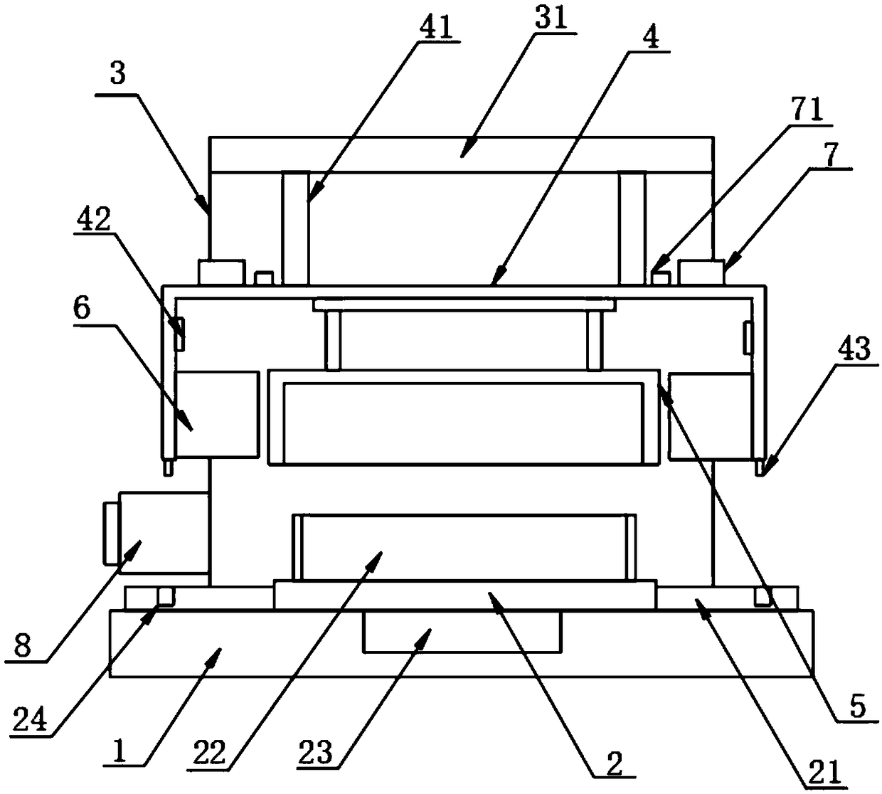
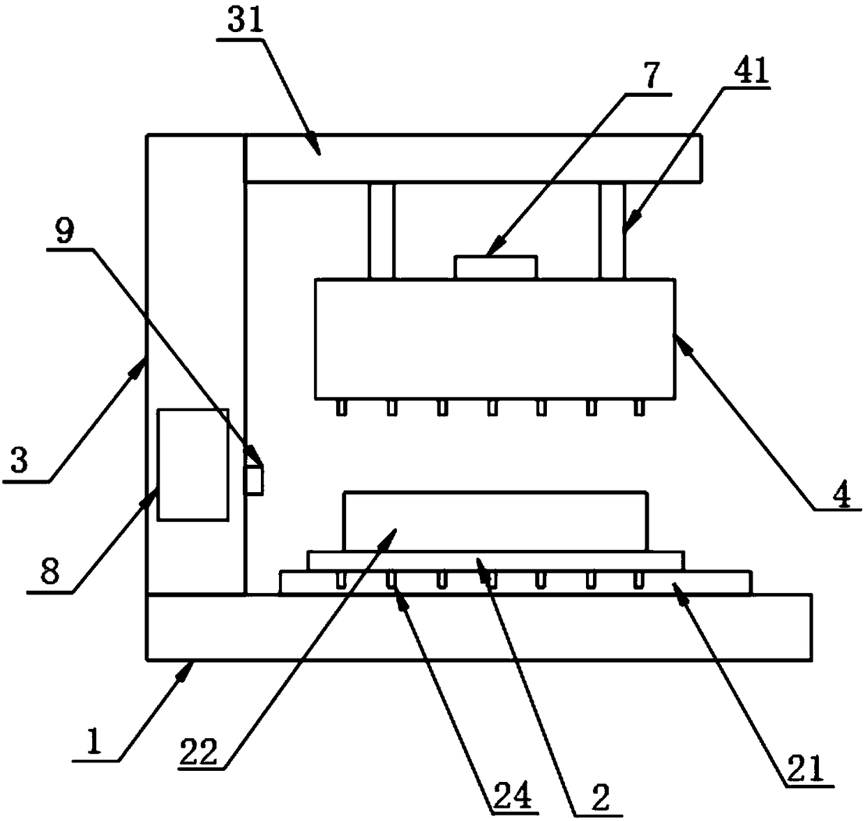
[0023] The present invention provides such Figure 1-4 The sand foundry die casting device shown includes a base 1, a movable plate 2 is provided on the top of the base 1, support plates 21 are provided on both sides of the movable plate 2, and side plates are provided on the rear side of the base 1 3. The top of the side plate 3 is provided with a top plate 31, and the bottom of the top plate 31 is provided with an elevating housing 4, and the elevating housing 4 is arranged on the top of the movable plate 2, and the inside of the elevating housing 4 is provided with a top mold 5 A cooling device 6 is provided on both sides of the inner wall of the lifting housing 4, and the cooling device 6 includes a fixed plate 61, a cooling housing 62, a second electric push rod 63, a liquid level gauge 64, a refrigerator 65, a liquid filling port 66 and heat conduction plate 67, the top of the lifting housing 4 is connected with a vacuum pump 7, and the side surface of the side plate 3 i...
Embodiment 2
[0029] Both the bottom mold 22 and the top mold 5 are made of copper alloy material, and the outside of the bottom mold 22 is connected with casting equipment through a casting pipeline.
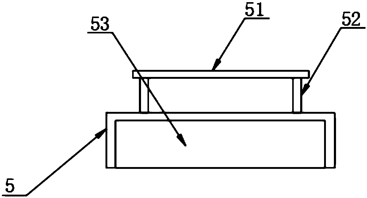
[0030] The top of the top mold 5 is provided with a mounting plate 51, and the mounting plate 51 is threadedly connected with the lifting housing 4 through fastening screws, and a first electric push rod 52 is uniformly arranged between the mounting plate 51 and the top mold 5, The inside of the top mold 5 is provided with a top mold cavity 53 .
[0031] Beneficial effects of this embodiment: the liquid casting material is injected into the bottom mold 22, and the motor 23 works to drive the movable plate 2 to shake slightly, so that the liquid casting material can move in the bottom mold 22 to ensure that the casting material can completely pass through the different parts in the bottom mold 22. Among the parts, the first electric push rod 52 pushes the top mold 5 to be close to the bottom ...
Embodiment 3
[0033] The fixed plate 61 is arranged on one side of the inner wall of the lifting shell 4, and a cooling shell 62 is arranged on one side of the fixed plate 61, and a second electric push rod 63 is uniformly arranged between the fixed plate 61 and the cooling shell 62 A liquid level gauge 64 is provided on one side of the inner wall of the cooling housing 62, a refrigerator 65 is provided at the bottom of the cooling housing 62, a liquid filling port 66 is provided at the top of the cooling housing 62, and a liquid level gauge 66 is provided at the top of the cooling housing 62. A heat conduction plate 67 is arranged on the outside, and the heat conduction plate 67 is arranged on both sides of the top mold 5 .
[0034] The surface of the PLC controller 8 is provided with a touch screen, and the connection end of the PLC controller 8 is evenly provided with a laser sensor 9 , and the laser sensor 9 is arranged on the front side of the side plate 3 .
[0035] Beneficial effects...
PUM
 Abstract
Description
Claims
Application Information
 - R&D Engineer
- R&D Manager
- IP Professional
- Industry Leading Data Capabilities
- Powerful AI technology
- Patent DNA Extraction
Browse by: Latest US Patents, China's latest patents, Technical Efficacy Thesaurus, Application Domain, Technology Topic, Popular Technical Reports.
© 2024 PatSnap. All rights reserved.Legal|Privacy policy|Modern Slavery Act Transparency Statement|Sitemap|About US| Contact US: help@patsnap.com