Mechanical equipment for automatically cutting steel bars

A mechanical equipment, automatic cutting technology, applied in the field of cutting machinery, can solve the problem of unsafe automatic cutting degree of steel cutting equipment, and achieve the effect of high degree of automation and reasonable action

Active Publication Date: 2018-12-21
GUANGDONG BOZHILIN ROBOT CO LTD
View PDF7 Cites 4 Cited by
  • Summary
  • Abstract
  • Description
  • Claims
  • Application Information

AI Technical Summary

Problems solved by technology

[0004] The purpose of the present invention is to solve the technical problems of the unsafe and low degree of automatic cutting of the existing steel bar cutting equipment, and provide a mechanical equipment for automatically cutting steel bars, which has a high degree of automation, and the cutting process does not require manual intervention, which is efficient and reliable

Method used


Image

  • Mechanical equipment for automatically cutting steel bars
  • Mechanical equipment for automatically cutting steel bars
  • Mechanical equipment for automatically cutting steel bars

Examples


Embodiment 1

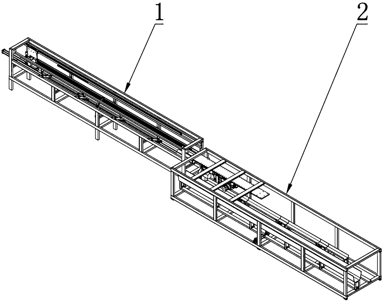
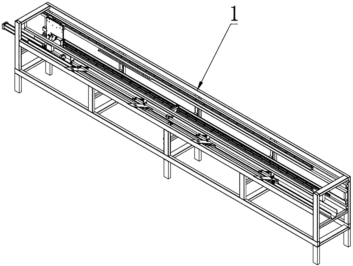
[0052] Such as Figure 1 to Figure 8 As shown, a mechanical device for automatically cutting steel bars according to the present invention includes a feeding device 1, a cutting device 2, a clamp set and an electrical control system connecting various functional devices. The feeding device 1 is used to connect the external steel bar conveyor belt, count and count the steel bars, feed a single steel bar each time, and push it into the cutting device 2 for accurate cutting according to the required length. During the cutting process, the two ends of the steel bar are compressed by the clamp group to avoid the bouncing and shaking of the steel bar. The cutting process of the mechanical equipment provided by the invention does not require manual intervention, is efficient and reliable, and the equipment is more suitable for one-time forming and cutting of long steel bars or steel pipes.

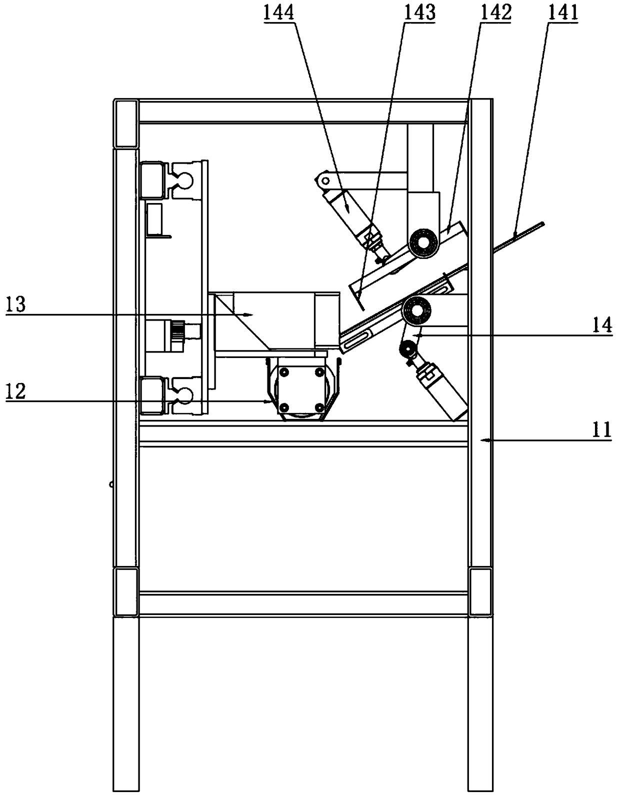
[0053] The feeding device 1 has a body consisting of a feeding frame 11 and a visible protec...

Embodiment 2

[0072] Embodiment 2 is a description of the electrical control system of the mechanical equipment for automatically cutting steel bars in Embodiment 1 above.

[0073] The electrical control system includes a PLC controller, a solenoid valve group of a cylinder, an operation panel and a detection sensor assembly. The PLC controller is respectively connected with the operation panel, the detection sensor assembly, the electromagnetic valve group and the feeding device, the cutting device and the electrical components in the clamp group in Embodiment 1. Realize the complete control loop of this mechanical equipment.

[0074] Specifically, the solenoid valve group is used to connect the pneumatic components in the feeding device, the cutting device and the clamp group with the external air supply source, and the action of each pneumatic component is controlled by PLC. The detection sensor assembly includes a first travel switch group, a second travel switch group, several magneti...


PUM


Abstract

The invention discloses mechanical equipment for automatically cutting steel bars. The mechanical equipment for automatically cutting steel bars comprises a feeding device, a cutting device and a clamp set. A feeding frame of the feeding device is provided with a feeding groove, a pushing mechanism and a feeding mechanism, and the pushing mechanism can reciprocate in a groove body of the feeding groove movably and can push the steel bars in the feeding groove to the cutting device. A cutting frame of the cutting device is provided with a cutting machine, an unloading mechanism and a storage groove, and the cutting device is correspondingly connected with the feeding device. The clamp set comprises a first clamp and a second clamp arranged on two sides of the cutting mechanism respectively.The first clamp is fixed to the feeding tail end of the feeding groove. The second clamp is arranged above the unloading mechanism in the mode of corresponding to the first clamp. The cutting frame is provided with a horizontal moving mechanism in driving connection with the second clamp so that the second clamp can reciprocate on the unloading mechanism. The mechanical equipment is high in automation degree, does not need manual intervention in the cutting process, and is efficient and reliable.

Description

technical field [0001] The invention belongs to the technical field of cutting machinery, and in particular relates to a mechanical device for automatically cutting steel bars. Background technique [0002] At present, with the rapid development of the economy, the development of industry and cities, a large number of houses are required to be built, and steel bars are used as an indispensable material in construction. Before use, it needs to be straightened and then cut to make the size of the steel bar meet the requirements of use. [0003] At present, the steel bar cutting equipment on the market has a complex structure, and the cutting operation also requires manual intervention. And the cutting method of the existing steel bar is sawing cutting, on the one hand need to manually measure the steel bar, start the cutting saw to complete the sawing operation. In this way, when the sawing length is constant, the steel bar needs to be measured every time. Because there is a...

Claims


Application Information

Patent Timeline
IPC IPC(8): B21F11/00
CPCB21F11/00
Inventor 孙军杨泓斌张亮亮高国恒樊晓
Owner GUANGDONG BOZHILIN ROBOT CO LTD
Why Eureka
Try Eureka