Fast sealing device used in mining and mixing spray gun of fast sealing device

A technology of mixed spraying and gun barrel, which is applied in the direction of spraying device and liquid spraying device, etc. It can solve the problems of pressure imbalance, material discharge ratio imbalance, and failure to achieve the sealing effect of the closed wall of the mine, so as to ensure the uniformity of mixing , flexible use, good fast sealing effect

Pending Publication Date: 2018-12-21
山西凝固力新型材料股份有限公司
View PDF6 Cites 3 Cited by
  • Summary
  • Abstract
  • Description
  • Claims
  • Application Information

AI Technical Summary

Problems solved by technology

[0002] In the conventional rapid sealing device in the prior art, the internal pressure of the A and B material storage tanks will decrease after being placed for a certain period of time, which will lead to the pressure imbalance in the A and B tanks, and the imbalance of the material discharge ratio in the A and B tanks, resulting in Polyurethane foam is soft and hard, and even unreacted material A or B appears, and the adhesion to the coal seam is greatly reduced, which cannot achieve the sealing effect of the closed wall of the mine
Simultaneously, the spray gun structure of the prior art is also unfavorable for the sufficient mixing of materials, and cannot ensure the mixing uniformity of the materials and the adhesion of the polyurethane foam to the coal seam. cannot be replaced in time

Method used


Image

  • Fast sealing device used in mining and mixing spray gun of fast sealing device
  • Fast sealing device used in mining and mixing spray gun of fast sealing device
  • Fast sealing device used in mining and mixing spray gun of fast sealing device

Examples


Embodiment Construction

[0085] Below in conjunction with accompanying drawing, structural principle and working principle of the present invention are specifically described:

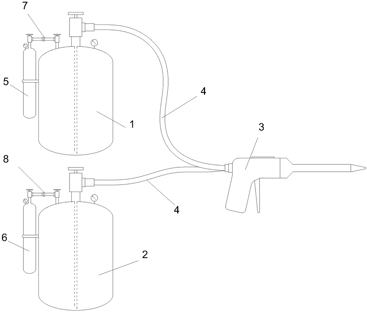
[0086] see figure 1 , figure 1 It is a structural schematic diagram of a quick sealing device for mines according to an embodiment of the present invention. The quick sealing device for mining of the present invention comprises a first storage tank 1, a second storage tank 2 and a mixing spray gun 3, and the first storage tank 1 and the second storage tank 2 communicate with the said first storage tank 1 through a pipeline 4 respectively. The mixing spray gun 3 is connected, the pipeline 4 is preferably a connecting hose, the first storage tank 1 is connected to the feed port 333 of the first feeding part 331 of the mixing spray gun 3, and the second storage The tank 2 is connected with the feeding port 333 of the second feeding part 332 of the mixing spray gun 3 . For example, both the first storage tank 1 and the second s...


PUM


Abstract

The invention discloses a fast sealing device used in mining and a mixing spray gun of the fast sealing device. The fast sealing device comprises a first storage tank and a second storage tank, whichare connected with the mixing spray gun. The mixing spray gun comprises a gun body and a mixing spray nozzle, wherein the gun body comprises a gun grip and a gun barrel; a feeding mechanism, control mechanisms and a gun-barrel quick connector are arranged on the gun barrel; the feeding mechanism comprises a first feeding part and a second feeding part; each of the first feeding part and the secondfeeding part comprises a feeding inlet, a feeding pipe and a material bin; the two ends of each feeding pipe are respectively connected with the corresponding feeding inlet and the corresponding material bin; a discharge outlet is formed in each material bin; each control mechanism is provided with an open position and a closed position, relative to the corresponding discharge outlet; the mixingspray nozzle comprises a spray-nozzle quick connector, a pipe body and a mixing mechanism; the spray-nozzle quick connector is detachably connected with the gun-barrel quick connector; one end of thepipe body is connected with the spray-nozzle quick connector, and a mixing discharge outlet is formed in the other end of the pipe body; the mixing mechanism is mounted in the pipe body; a material-separating baffle plate is arranged between the mixing mechanism and the material bins and positioned between the discharge outlet of the material bin of the first feeding part and the discharge outletof the material bin of the second feeding part.

Description

technical field [0001] The invention relates to a mine airtight device, in particular to a quick mine airtight device and a mixing spray gun for quickly establishing a polyurethane rigid foam plastic airtight wall underground in a coal mine. Background technique [0002] In the conventional fast sealing device in the prior art, the internal pressure of the A and B material storage tanks will decrease after being placed for a certain period of time, which will cause the pressure imbalance in the A and B tanks, and the output ratio of the materials in the A and B tanks will be out of balance, resulting in Polyurethane foam is not uniform in hardness and softness, and even unreacted material A or material B appears, and the adhesion to the coal seam is also greatly reduced, which cannot achieve the sealing effect of the closed wall of the mine. Simultaneously, the spray gun structure of the prior art is also unfavorable for the sufficient mixing of materials, and cannot ensure ...

Claims


Application Information

Patent Timeline
Patent Type & Authority Applications(China)
IPC IPC(8): B05B7/04B05B7/24B05B7/26B05B15/60
CPCB05B7/0408B05B7/2491B05B7/267B05B15/60
Inventor 王建中王涛
Owner 山西凝固力新型材料股份有限公司
Why Eureka
Try Eureka