
Centrifugal micro-fluidic splitter

A technology of microfluidic devices and microfluidic chips, applied in the field of microfluidics, can solve the problems of incompetence in real-time signal reading, serial pollution, etc.

Pending Publication Date: 2018-12-21
深圳市呈晖医疗科技有限公司
View PDF13 Cites 6 Cited by
  • Summary
  • Abstract
  • Description
  • Claims
  • Application Information

AI Technical Summary

Problems solved by technology

In addition, the current centrifugal microfluidics is hardly capable of real-time reading of the signal of the detection chamber in the disc chip in the high-speed centrifugal state.
[0006] In traditional centrifugal microfluidics, in order to avoid serial contamination of different samples in the subsequent liquid manipulation, a single disc chip can often only process a single sample

Method used


Image

  • Centrifugal micro-fluidic splitter
  • Centrifugal micro-fluidic splitter

Examples


Embodiment Construction

[0022] In order to facilitate the understanding of the present invention, and to make the above objects, features and advantages of the present invention more obvious and understandable, the specific implementation manners of the present invention will be described in detail below in conjunction with the accompanying drawings. In the following description numerous specific details are set forth in order to provide a full understanding of the invention, and preferred embodiments of the invention are shown in the accompanying drawings. However, the present invention can be embodied in many different forms and is not limited to the embodiments described herein. On the contrary, the purpose of providing these embodiments is to make the disclosure of the present invention more thorough and comprehensive. The present invention can be implemented in many ways other than those described here, and those skilled in the art can make similar improvements without departing from the connota...


PUM


Abstract

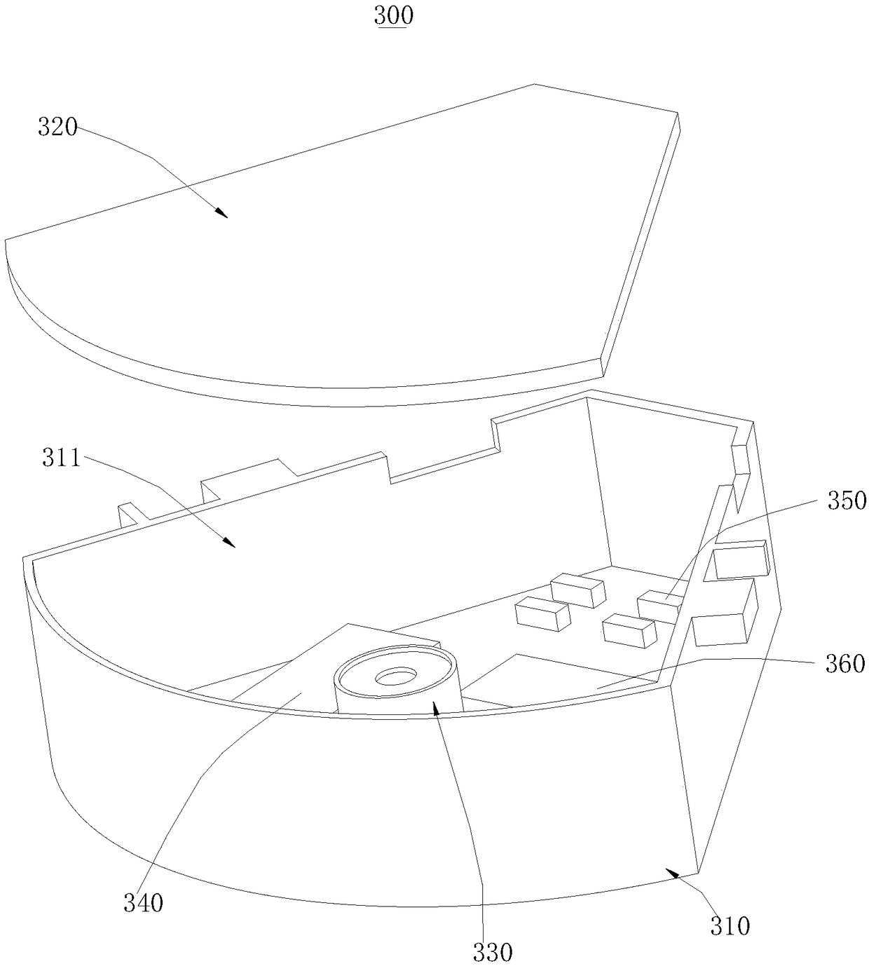
The invention provides a centrifugal micro-fluidic splitter. The centrifugal micro-fluidic splitter comprises a centrifugal driving mechanism, a plurality of connection pieces and a plurality of detection card boxes; the centrifugal driving mechanism is provided with a centrifugal rotary shaft; the first ends of the connection pieces are connected with the centrifugal rotary shaft; the detection card boxes comprise box bodies, box covers, photoelectric sensors and temperature control modules, the box bodies are provided with cavity structures with one ends being open, the photoelectric sensorsand the temperature control modules are all arranged on the side walls of the corresponding cavity structures, micro-fluidic chips are located in the cavity structures of the box bodies, and the photoelectric sensors align the detection cavities of the micro-fluidic chips. The micro-fluidic splitter is characterized in that the capacity of the cavity structures of the box bodies is smaller, the temperature control modules can control the temperature more precisely and are particularly suitable for biochemical reactions which are sensitive to temperature reactions, and accordingly the detection results are more precise. Due to the positions of the photoelectric sensors and the micro-fluidic chips are relative still, accordingly the photoelectric sensors can detect the photoelectric signalsof the detection cavities of the micro-fluidic chips.

Description

technical field [0001] The invention relates to the field of microfluidic technology, in particular to a centrifugal microfluidic device. Background technique [0002] Microfluidics refers to the manipulation of liquids on the submillimeter scale, generally in the range of a few microns to hundreds of microns. Microfluidics integrates the basic operating units involved in the fields of biology and chemistry, and even the entire assay operation, including sampling, dilution, reaction, separation, detection, etc., on a small chip, so it is also called Lab-on-a-Chip (Lab-on-a-chip). -a-Chip). This kind of chip is generally composed of various liquid storage pools and interconnected microchannel networks, which can greatly shorten the sample processing time, and realize the maximum utilization efficiency of reagent consumables through precise control of liquid flow. Microfluidics provides extremely broad prospects for applications in many fields such as biomedical research, dr...

Claims


Application Information

Patent Timeline
Patent Type & Authority Applications(China)
IPC IPC(8): B01L3/00
CPCB01L3/5025B01L3/5027
Inventor 汤明辉
Owner 深圳市呈晖医疗科技有限公司
Learn More