Novel running machine for physical exercise

A technology of physical exercise and treadmill, which is applied in gymnastics equipment, training equipment for adjusting the cardiovascular system, training equipment for adjusting coordination, etc., and can solve problems such as unsatisfactory and inability to adjust the speed of the treadmill

Active Publication Date: 2018-12-21
郑招才
View PDF5 Cites 0 Cited by
  • Summary
  • Abstract
  • Description
  • Claims
  • Application Information

AI Technical Summary

Problems solved by technology

[0002] For example, the patent No. CN201420561826.0 is a treadmill for physical exercise, which belongs to the technical field of sports equipment, including high-quality stainless steel columns, and is characterized in that a safety handrail is provided on the high-quality stainless steel column, and a simulated skin sheath is provided on the safety handrail, which is high-quality. One end of the stainless steel column is provided with a stable support rod, and a spare load rack is provided on the stable support rod. The sit-up hook is provided on the spare load rack, and the sit-up hook is equipped with a hook cotton. High-quality stainless steel The upper end of the column is provided with a main box, the main box is provided with an operation panel, the operation panel is provided with an LED display, and the lower end of the LED display is provided with a switch button. Requirements for different running speeds

Method used


Image

  • Novel running machine for physical exercise
  • Novel running machine for physical exercise
  • Novel running machine for physical exercise

Examples


specific Embodiment approach 1

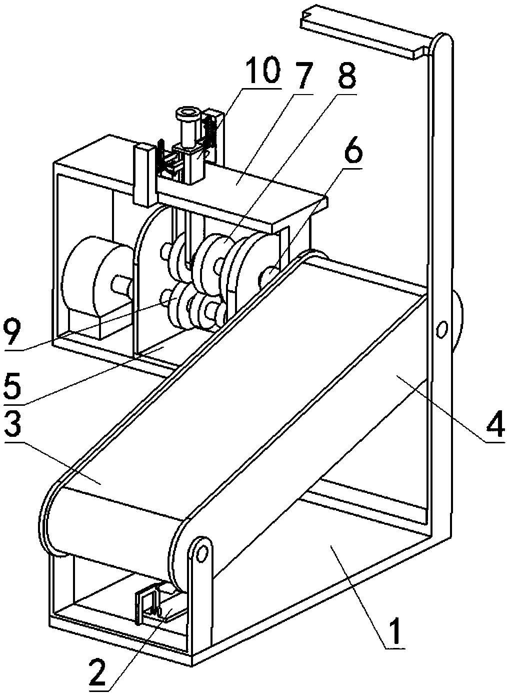
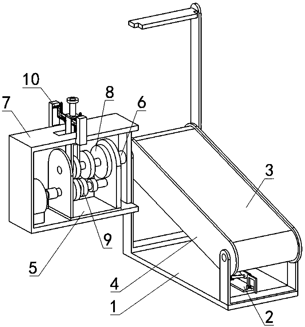
[0037] Combine below Figure 1-16 Describe this embodiment, a new type of treadmill for physical exercise, including a bracket assembly 1, a mechanical dead point clamping mechanism 2, a running belt 3, a running belt outer frame combination 4, a power frame 5, a sliding hole coupling 6, The fixed outer frame 7, the sliding rotating rod 8, the transmission rod 9 and the switch pressing combination 10 are characterized in that: the front end of the mechanical dead point clamping mechanism 2 is fixedly connected to the front end of the upper end surface of the bracket assembly 1, and the running belt The front and rear ends of the frame combination 4 are respectively rotatably connected to the front and rear ends of the bracket combination 1, the front and rear ends of the inner wall of the running belt 3 are respectively connected to the front and rear ends of the running belt outer frame combination 4 through interference fit, and the power frame 5 is fixedly connected. At the...

specific Embodiment approach 2

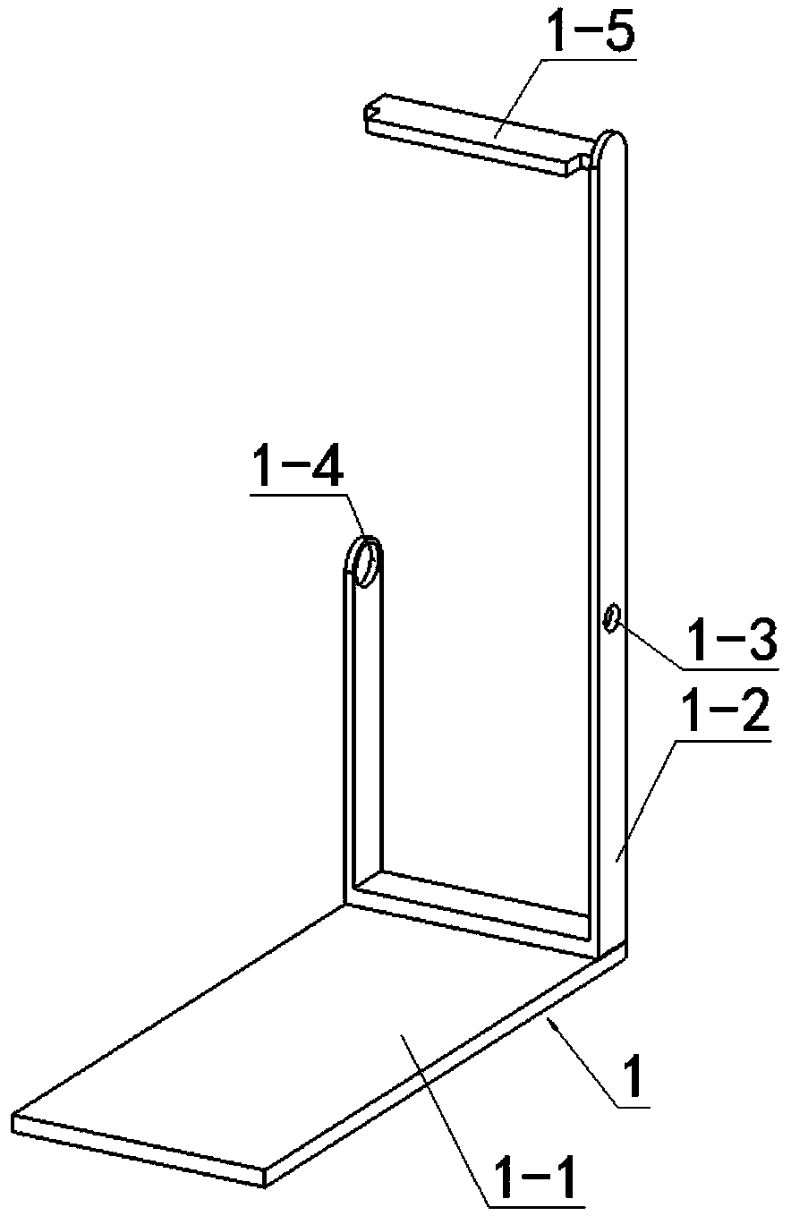
[0038] Combine below Figure 1-16 This embodiment will be described. This embodiment will further describe the first embodiment. The bracket assembly 1 includes a bottom plate 1-1, a bracket rod 1-2, a right rotation hole 1-3, a left rotation hole 1-4 and an upper The side hanging rod 1-5, the support rod 1-2 is fixedly connected to the rear end of the upper end surface of the bottom plate 1-1, the right turning hole 1-3 is arranged at the middle end of the right end surface of the inner wall of the support rod 1-2, and the upper side hanging rod 1-5 is fixedly connected to the upper end of the support rod 1-2, and the left turning hole 1-4 is arranged on the upper side of the left end of the support rod 1-2;

[0039] The bottom plate 1-1 can be conveniently fixed and connected to the bracket rod 1-2; the right rotating hole 1-3 can facilitate the rotating connection of the upper rotating shaft 4-6; the left rotating hole 1-4 can facilitate the sliding hole coupling body 6- 1...

specific Embodiment approach 4

[0042] Combine below Figure 1-16 Describe this embodiment, this embodiment will further explain the third embodiment, the running belt outer frame combination 4 includes a work-shaped bracket 4-1, a lower side roller 4-2, a lower side rotating shaft 4-3, and a hinged pole 4 -4, the upper side roller 4-5 and the upper side rotating shaft 4-6, the lower side rotating shaft 4-3 and the upper side rotating shaft 4-6 are respectively rotated and connected to the upper and lower ends of the I-shaped support 4-1, and the lower side roller 4- 2. It is fixedly connected to the lower rotating shaft 4-3. The lower roller 4-2 is arranged at the middle end of the lower end surface of the I-shaped support 4-1. The left and right ends of the hinged support rod 4-4 are respectively connected to the lower rotating shaft 4-3 in rotation. The left and right ends of the upper side roller 4-5 are rotatably connected on the upper side shaft 4-6, and the upper side roller 4-5 is arranged on the inn...


PUM


Abstract

The invention relates to a running machine for exercise, in particular to a novel running machine for physical exercise. The speed of the running machine can be adjusted, and the demand of exercisersfor different running speeds can be met. The running machine comprises a supporting combination body, a mechanical dead point clamping mechanism, a running belt, a running belt outer frame combination, a power frame, a slide hole coupler, a fixing outer frame, a sliding rotation rod, a transmission rod and a switching press combination. A support rod can be conveniently and fixedly connected to abaseplate; a rotation hole of the right side is conveniently and rotatably connected with a rotation shaft of the upper side; a rotation hole of the left side is conveniently and slidingly connected with a slide hole coupler body; a hinge end of the front side is conveniently hinged to an n-shaped press rod; a hinge end of the rear side is conveniently hinged to a connection rod; a manual rotationrod is conveniently connected with the n-shaped press rod and the connection rod; the junction of the n-shaped press rod and the manual rotation rod, the junction of the manual rotation rod and the connection rod and the junction of the connection rod and the hinge end of the rear side are located on the same straight line, and a hinge supporting rod can be fixed and locked through the position of a mechanical structure dead point.

Description

technical field [0001] The invention relates to a treadmill for exercise, more specifically a new type of treadmill for physical exercise. Background technique [0002] For example, the patent No. CN201420561826.0 is a treadmill for physical exercise, which belongs to the technical field of sports equipment, including a high-quality fine steel column, which is characterized in that a safety armrest is provided on the high-quality fine steel column, and a simulated skin sheath is provided on the safety armrest, and the high-quality One end of the stainless steel column is provided with a stable support rod, and a spare load rack is provided on the stable support rod. The sit-up hook is provided on the spare load rack, and the sit-up hook is provided with hook cotton. High-quality stainless steel The upper end of the column is provided with a main box, the main box is provided with an operation panel, the operation panel is provided with an LED display, and the lower end of th...

Claims


Application Information

Patent Timeline
IPC IPC(8): A63B22/02
CPCA63B22/0257
Inventor 郭子军
Owner 郑招才
Why Eureka
Try Eureka