
Antenna circuit, control method and device of mobile terminal

A mobile terminal, antenna circuit technology, applied in the direction of circuit, antenna, antenna coupling, etc., can solve the problems of poor antenna efficiency, low multi-antenna isolation, etc., to reduce interference and solve the effect of low isolation

Active Publication Date: 2018-12-18
VIVO MOBILE COMM CO LTD
View PDF15 Cites 19 Cited by
  • Summary
  • Abstract
  • Description
  • Claims
  • Application Information

AI Technical Summary

Problems solved by technology

[0004] Embodiments of the present invention provide an antenna circuit, control method and device for a mobile terminal to solve the problem of poor antenna efficiency caused by too low isolation between multiple antennas

Method used


Image

  • Antenna circuit, control method and device of mobile terminal
  • Antenna circuit, control method and device of mobile terminal
  • Antenna circuit, control method and device of mobile terminal

Examples


Embodiment Construction

[0026] The following will clearly and completely describe the technical solutions in the embodiments of the present invention with reference to the accompanying drawings in the embodiments of the present invention. Obviously, the described embodiments are some of the embodiments of the present invention, but not all of them. Based on the embodiments of the present invention, all other embodiments obtained by persons of ordinary skill in the art without creative efforts fall within the protection scope of the present invention.

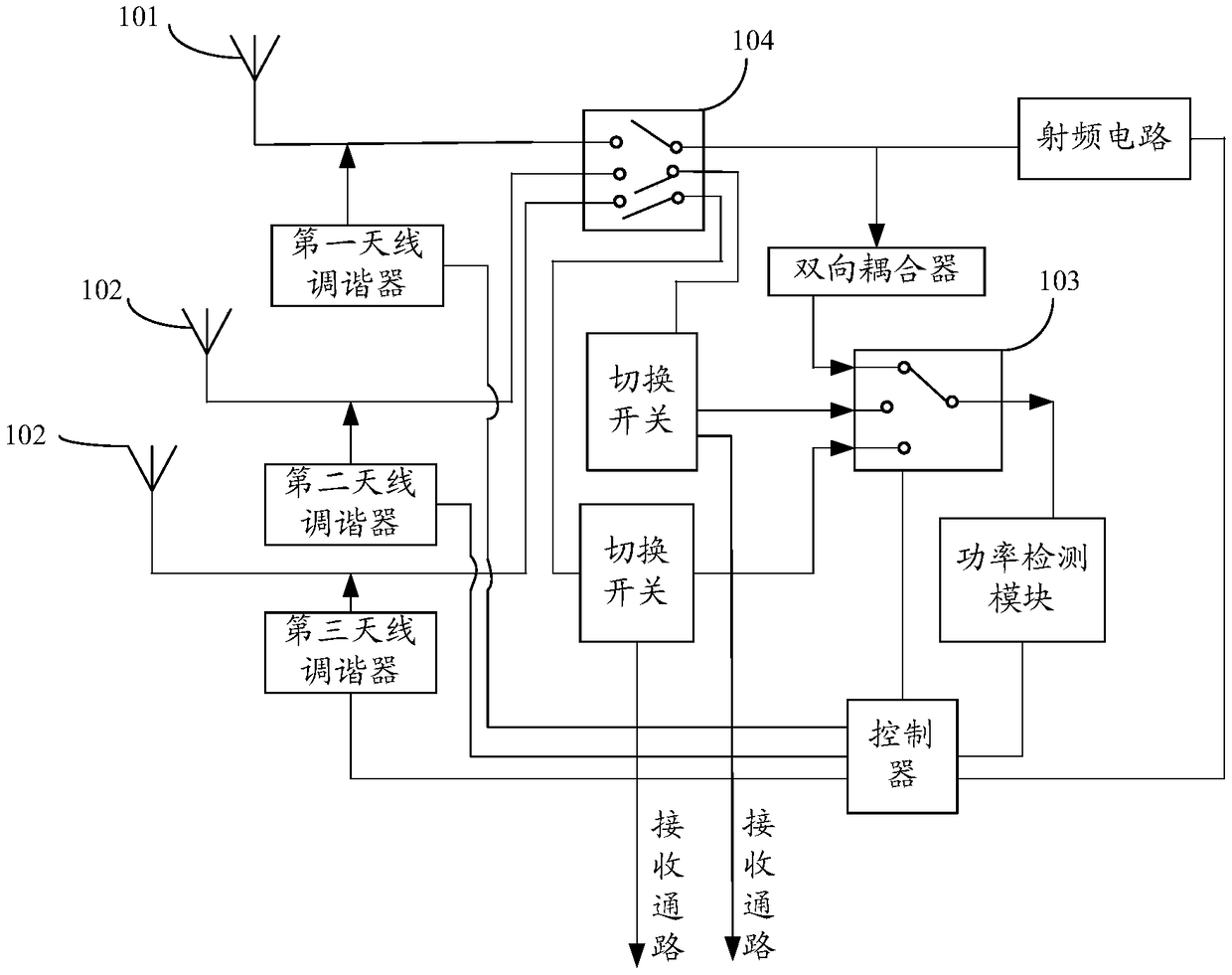
[0027] Embodiments of the present invention provide an antenna circuit for a mobile terminal, such as figure 1 As shown, the antenna circuit of the mobile terminal includes:

[0028] At least two antennas, wherein each antenna is respectively connected to an antenna tuner;

[0029] a radio frequency circuit, the radio frequency circuit is electrically connected to the first antenna 101 of the at least two antennas;

[0030] A power detection module, ...


PUM


Abstract

The invention provides an antenna circuit, a control method and a device of a mobile terminal. The antenna circuit comprises at least two antennas, wherein, each antenna is respectively connected withan antenna tuner; a radio frequency circuit electrically connected to a first antenna of the at least two antennas; a power detection module connected with a radio frequency circuit; a receiving path, wherein each of the at least two antennas other than the first antenna is connected to the receiving path through a switching switch, and each switching switch is connected to a power detection module; a controller respectively connected with the power detection module and the antenna tuner. Therefore, the scheme of the invention solves the problem that the isolation between the multiple antennas is too low and the antenna efficiency is poor.

Description

technical field [0001] The present invention relates to the technical field of mobile communication, in particular to an antenna circuit, a control method and a device of a mobile terminal. Background technique [0002] Currently, mobile terminals need to support more and more frequency bands. Therefore, in order to improve antenna efficiency, most terminals adopt antenna division technology, resulting in an increase in the number of antennas. In addition, with the continuous evolution and iteration of communication technology, Multiple-Input Multiple-Output (MIMO) technology is gradually introduced into commercial use, and terminal support for MIMO technology is the mainstream trend, from 2X2MIMO to mainstream 4X4MIMO, or to N X N MIMO on the back. [0003] Among them, the fixed shape of the terminal determines that the antenna space is limited, which makes the dense antenna distribution lead to a series of problems, such as the low isolation between MIMO antennas affects...

Claims


Application Information

Patent Timeline
Patent Type & Authority Applications(China)
IPC IPC(8): H04B7/0404H04B1/40H04B1/00H01Q23/00H01Q21/00H01Q1/52
CPCH01Q1/521H01Q21/00H01Q23/00H04B1/006H04B1/40H04B7/0404
Inventor 刘彬彬
Owner VIVO MOBILE COMM CO LTD
Learn More