Auxiliary wiring equipment for electric aerial work

A technology for high-altitude operation and auxiliary wiring, which is applied to the equipment for connecting/terminating cables, etc., which can solve the problems of time-consuming and laborious, insufficient adjustment position accuracy, and danger.

Active Publication Date: 2020-08-21
山东源泰电力科技有限公司
View PDF4 Cites 0 Cited by
  • Summary
  • Abstract
  • Description
  • Claims
  • Application Information

AI Technical Summary

Problems solved by technology

There is serious risk deficiency in this construction method:
[0004] 1. Since the fixed wiring is suspended in the air as a whole, under the action of gravity, there is a large pulling force at the fixed wiring and the pulley. Because the strength of the construction personnel is limited, this pulling force makes it impossible to adjust the position of the pulley where the fixed wiring is located, and the construction personnel can only adjust it. The position of the pulley where the wire to be connected is used to make the relative position between the fixed wiring and the wire to be connected suitable. However, it takes a lot of effort to adjust the position of the pulley where the wire to be connected is located, because the suspended wire to be connected is also relatively large. Large weight, and due to the inertia when adjusting the position of the pulley, it is necessary to apply force slowly to adjust the position
The operation during the entire adjustment construction process is difficult and dangerous, and it is very labor-intensive
[0005] 2. Two separate pulleys are used for construction, and it is inconvenient for users to control at the same time
[0006] 3. The distance between the fixed wiring and the wires to be connected can only be manually adjusted by adjusting the position of the pulley where the wires to be connected are located, and the accuracy of the adjustment position is not enough. Repeated adjustments are required to achieve a reasonable wiring position, resulting in construction The process is time-consuming and laborious

Method used


Image

  • Auxiliary wiring equipment for electric aerial work
  • Auxiliary wiring equipment for electric aerial work
  • Auxiliary wiring equipment for electric aerial work

Examples


Embodiment Construction

[0035] Below in conjunction with specific embodiment, further illustrate the present invention. It should be understood that these examples are only used to illustrate the present invention and are not intended to limit the scope of the present invention. In addition, it should be understood that after reading the content taught by the present invention, those skilled in the art may make various changes or modifications to the present invention, and these equivalent forms also fall within the scope defined in the present application.

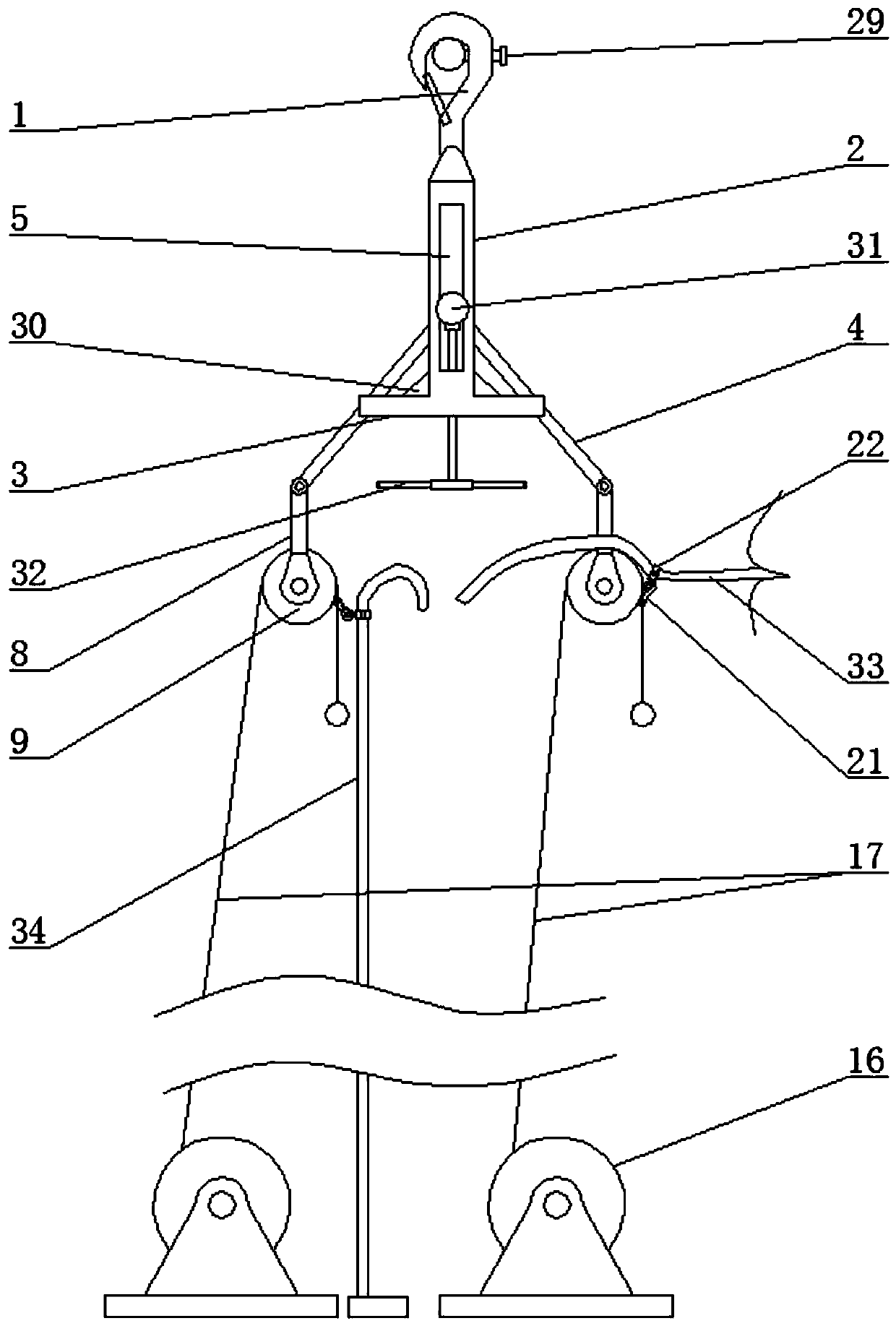
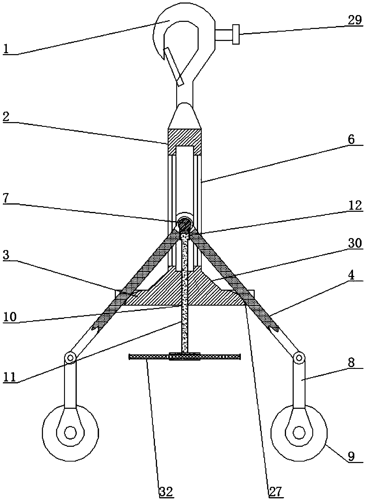
[0036] The present invention is an auxiliary wiring device for electric high-altitude operations. The main structure includes a cross-arm hook 1, a square hollow vertical tube 2, an overlapping projection 3, hinged rods 4 on both sides of the square hollow vertical tube 2, a pulley assembly and Adjusting device assembly, electric winding mechanism;

[0037] The bottom end of the cross arm hook 1 is fixed on the top of the square hollow vertical p...


PUM


Abstract

The invention discloses an auxiliary wiring device for electric power high-altitude operation, which mainly relates to the field of high-altitude auxiliary wiring device. Comprises a cross arm hook, asquare hollow vertical pipe, an overlapping protrusion, hinged rods on both sides of the square hollow vertical pipe, a pulley device assembly and an adjusting device assembly, and an electric winding mechanism; A hinge shaft is slidably connected with the sliding hole of the shaft part, and two hinge rods are symmetrically arranged; The pulley device assembly is provided with two pulleys; The adjusting device assembly comprises an adjusting bolt and a limiting cap; The electric winding mechanism comprises a servo motor, a winding wheel and a lifting rope. The invention has the advantages that the shortcomings in the prior art are solved, and the fixing wiring, the electric wire to be connected and the fixing work after the connection can be more conveniently carried out.

Description

technical field [0001] The invention relates to the field of high-altitude auxiliary wiring devices, in particular to auxiliary wiring equipment for electric high-altitude operations. Background technique [0002] In the erection and maintenance of the power grid, high-altitude wiring operations are the most frequent operations. There are two types of high-altitude wiring operations, one is to wire the cable hoops on the utility poles or towers or to connect the wires to insulators. The high-altitude wiring work of connecting wires to guy hoops or insulators is relatively simple, because the guy hoops or insulators are fixed on iron cross arms or towers, and the work can be completed after connecting the wires to the guy hoops or insulators . [0003] The second is to connect the ends of the two wires with a connector, and then use steel wire ropes to fix the wired connector to the iron cross arm or the electric tower. For such high-altitude wiring operations, it is very ...

Claims


Application Information

Patent Timeline
Patent Type & Authority Patents(China)
IPC IPC(8): H02G1/14
CPCH02G1/14
Inventor 韩衍军马化臻刘义强刘太朋
Owner 山东源泰电力科技有限公司
Why Eureka
Try Eureka