
Optical switch button

A technology of optical switches and keys, applied in the direction of electric switches, electrical components, circuits, etc., can solve the problems of metal sheet or metal contact corrosion, poor conduction, affecting the stability of keys, etc., to avoid the interference of external light, accurate The conversion of pressing signals and the effect of improving the correctness of operation

Active Publication Date: 2018-12-18
DARFON ELECTRONICS (SUZHOU) CO LTD +1
View PDF3 Cites 8 Cited by
  • Summary
  • Abstract
  • Description
  • Claims
  • Application Information

AI Technical Summary

Problems solved by technology

However, metal sheets and metal contacts are prone to wear and tear due to impact, which affects the service life of the buttons, and also causes metal sheets or metal contacts to rust due to moisture, resulting in poor conduction and affecting the stability of the buttons.
Furthermore, conventional mechanical buttons are generally not suitable for portable electronic devices that require high thinness, such as notebook computers, due to their complex structure and large volume.

Method used


Image

  • Optical switch button
  • Optical switch button
  • Optical switch button

Examples


Embodiment Construction

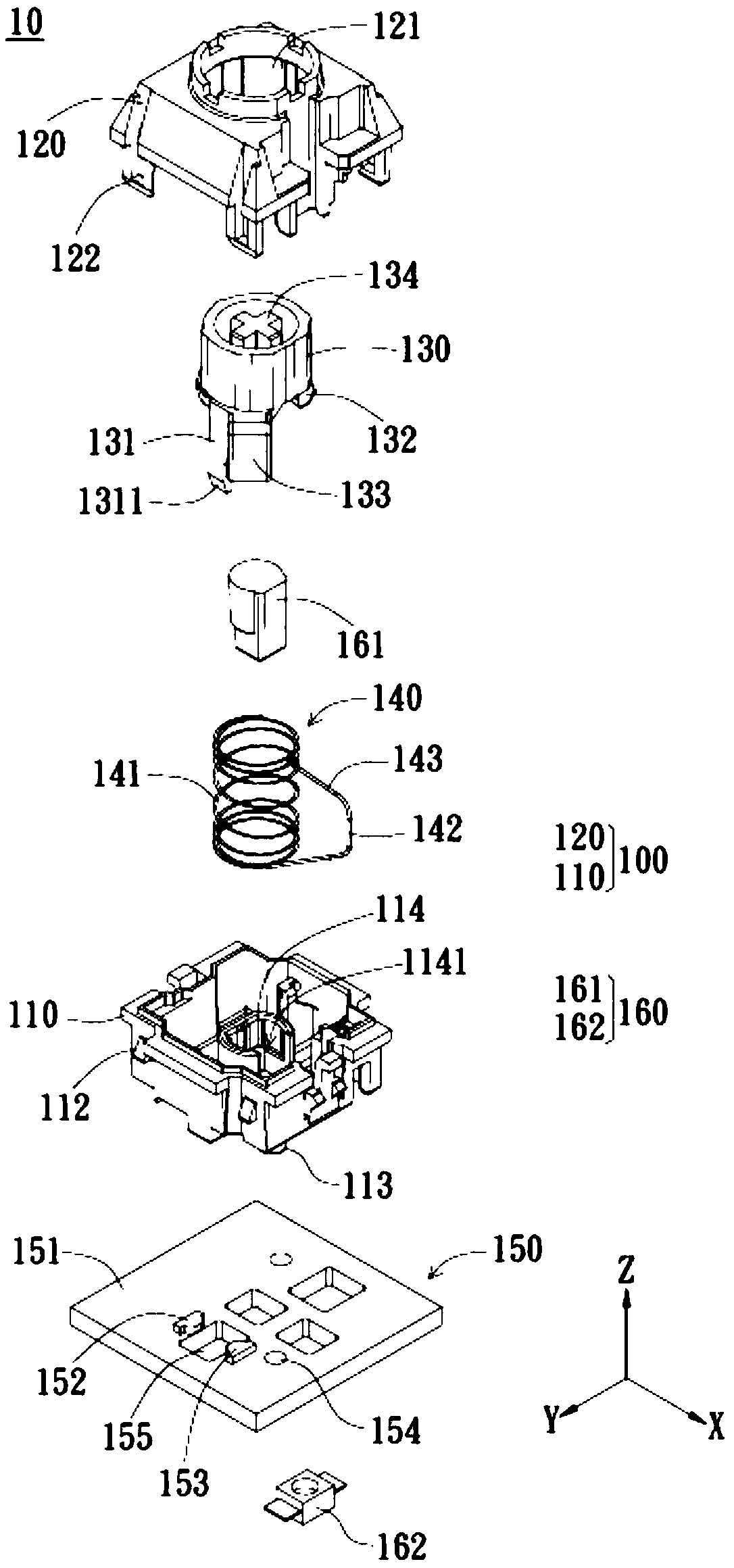
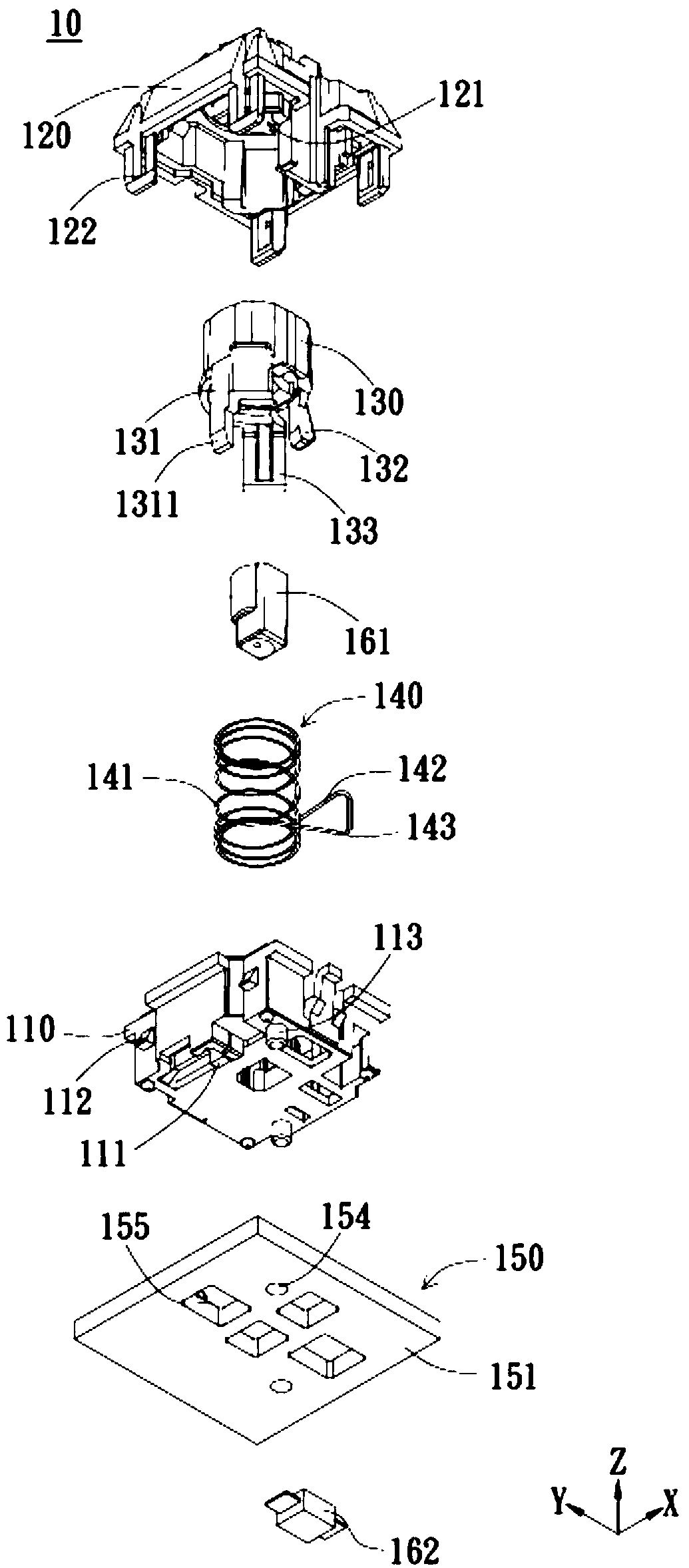
[0065] The present invention provides an optical switch button, which can be applied to any push-type input device (such as a keyboard), or integrated into any suitable electronic device (such as a button of a portable electronic device or a keyboard of a notebook computer) to provide fast And precise trigger function, and suitable for a variety of button structure design. The structure and operation of each component of the optical switch button according to the embodiment of the present invention will be described in detail below with reference to the drawings.

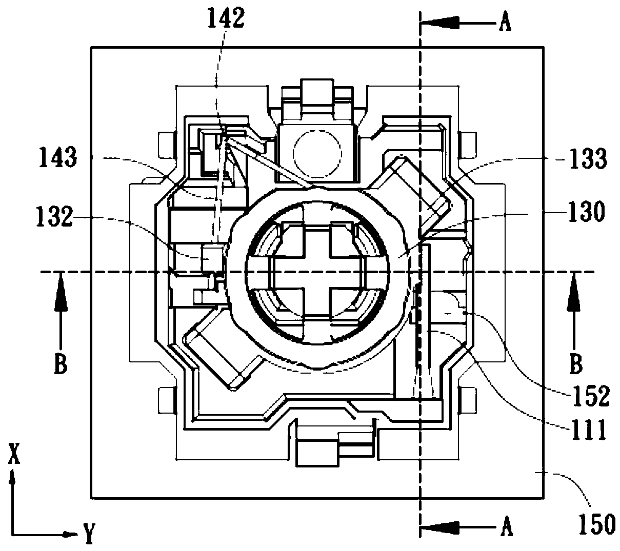
[0066] Figure 1A to Figure 5D is a schematic diagram of the first embodiment of the present invention, wherein Figure 1A and Figure 1B are explosion schematic diagrams of the optical switch buttons in different viewing angles according to the first embodiment of the present invention, and Figure 1C for Figure 1A The optical switch button does not show the combined top view of the upper shell, and Figure 1D ...


PUM


Abstract

The invention discloses an optical switch button. The button contains a deformable housing, a movable shaft arranged in the housing, an elastic part arranged in the housing and equipped with a circuitboard, a light emitter and a switch button of a light receiver. The movable shaft is selectively disposed at the non-pressed position and the pressed position. The light emitter emits a light signal.The light signal reaches the light receiver along a light transmission path. When the movable shaft is at the non-pressed position, a deformable part and the light transmission path are in the firstspace relationship. The light signal received by the light emitter is first strength. When the movable shaft moves to the pressed position from the non-pressed position by press pressure, the movableshaft compresses an elastic part and pushes against the deformable part to move. Therefore, the light signal received by the light receiver is second intensity different from the first intensity. As aresult, the switch button is trigged to generate a trigger signal. The button can quickly and precisely convert press signals.

Description

technical field [0001] The invention relates to an optical switch key, in particular, the invention relates to an optical switch key which actuates a switch in response to a change in the receiving state of an optical signal due to a pressing action. Background technique [0002] Membrane switch keys and mechanical keys are commonly used key types in conventional keyboards. The main difference between the membrane switch button and the mechanical button is that the circuit structure that generates the signal is different. Generally speaking, a membrane switch button is a switch component that uses a thin film circuit layer as a signal generator. When the keycap is pressed to trigger the thin film circuit layer, the upper circuit layer is deformed so that the switch contacts of the upper circuit layer contact the corresponding switch contacts of the lower circuit layer. Then the membrane switch is turned on to generate a signal. However, the thin-film circuit layer is easil...

Claims


Application Information

Patent Timeline
Patent Type & Authority Applications(China)
IPC IPC(8): H01H13/14H01H13/83
CPCH01H13/14H01H13/83H01H13/705
Inventor 王勇智谢育群杨宸刘家宏
Owner DARFON ELECTRONICS (SUZHOU) CO LTD
Learn More